Attention Space2000..... earth calling!
Are you there dear Space.... please land and have attention.
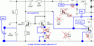
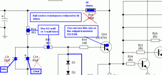
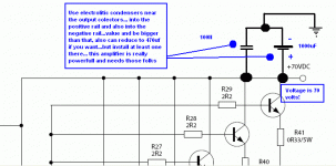
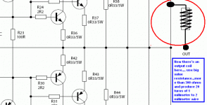
This one, the modifications shown, they consists into the last schematic.... the DHR TURBO REVISION 2.... the last final schematic... the ultimate... the last one made... the final from the last schematic about this amplifier.
Only error correction will be done in the future....but not modifications..only if there's is serious errors.
Last, final, more recent, updated, upgraded schematic is this one attached bellow... not the one you are following.
regards,
Carlos
Attachments
DHR Turbo, upgraded and updated schematic is here
A very kind offer from Mr. Todd Johnson... excelent work dear Todd.
Thank you very much.
This schematic was the result of tuning, upgrade, update, calibration, adjustment, fine tuning, tweaking, testing, listening and it is ready to go.
Enjoy this nice amplifier, and prepare the boot...to give a kick in your old amplifier.
This schematic will be sent to Greg Erskine and will be into his site very soon.
http://users.tpg.com.au/users/gerskine/dxamp/
Of course, www.dxamp.com is an official site, with Nordic/ Nico, the world distribution Offices, PCBoard design Division, and acessories creation... it may be found there too, and soon.
regards,
Carlos
Attachments
dear DX,
when ever i checked, i found different in all diagrams. i was confused then went to your website and downloaded that version. anyway, i am not sad about it. you have given lots of afforts to do this, wrong i made, it dsn't mtr to me, i can reconstruct it right? tomorrow may be i have to buy some more parts again. thanks for you help.
i am bad boy thats why can learn somethings. ppls learn from mistake, dear. i like to learn. so mistake i made that you..for making correct. i love it.
i tell you one good things.
your amp two cheannel surely can go on to my space heat sink. i checked even the bias was 0.646mill volt, believe me....it even dosn't get hot at all. wow....i was so much surprise. same bias was on my another heat sink 9"X7" inch the heat sink within one mint went to 106c. my this heat sink "space" is a huge capable of heat recivng. i can understand this. now compare by your self.
here is a test showing for heat sink.
base on voltage on E-B Power transistor 0.646 (amplifier). it is quite high right?
my amb is 30c. compare on two heat sink.
heat sink 9"X7" huge construction solid = one mint went to 103c (6 transistors on it)
heat sink "space" 12" dia = 31c after one mints. (8 transistors on it)
now judge by your self. i never on the fan.
best regards
michael
Attachments
Oh!.... good results!...yes... this VBE is a little bit high...but works this way too
Not a very good VBE...i would make some effort to reduce it, at least to 620 milivolts....but better is 575 milivolts as i could find trying here many kind of VBE voltages into those transistors.
Good, i see you are very good working with metals...so...everything is under control.... everything fine.
Good!
regards,
Carlos
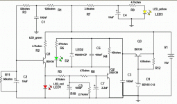
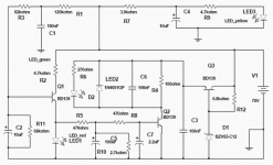
Speaker delayed insertion after seconds of power on
The DHR amplifier has spectacular response to transients.
the result of that, is that when you switch the power on you
will listen a huge “tac” sound into the speaker, as this
disturbance will be amplified… this good thing to audio is
annoying before the music play…so…I have created a delay,
using a relay… this was not assembled, not tested, will work
for sure but may need electrolitic condenser values adjustment
to tune it to work tuned to your needs.
This works when you switch your supply switch power on…
some delay will make the relay switch the speaker into
the circuit after all disturbance was already finished, and
long time after the amplifier had received power and all circuit
is stabilized…. So… the speaker goes on because of the relay
action.
When you switch power on, the positive goes through R7 and
start to charge C4… during this charging time the voltage will
be small and growing and cross 4K7 and going to the yellow
red, will make it on after 1 second more or less…this is there
only as a helpful indication that your amplifier is receiving energy,
as this circuit receive 70 volts from your power amplifier supply
at same time, the positive crosses R1 and fast charge C1, and this
one is a transient noises filter only… the positive continues flowing
and cross R3 and goes charging C2… some energy flows througth
R11 and this one is a drain that delays C2 charging time and also
helps to discharge C2 to the ground when the circuit not receive
energy. During C2 charging period, Q1 base to emitter junction
is conducting a very small energy, not enougth to ligth the red led
into ligth…but… after the voltage from base to emitter reaches
something near 600 milivolts, bigger energy will flow from coletor
to emitter and will make this red led on…also voltage over this
Led turns bigger and will go via R5 to charge C5 that will have
a charging delay caused by R10… this same R10 will work to
discharge C5 when your supply power is off…. The energy goes
crossing R8 delayed by C7 charge and will go biasing transistor
Q2…. The voltage will grown till make this transistor switch on…
off course delayed… there’s a sequence of leds going to ligth..
first the yellow one…then the red and very fast after this last one
the green led will ligth..means the relay is on and your
speaker goes to the power amplifier output circuit using relay contacts
The transistor Q3 works as a series regulator to reduce the 70 volts
to 12 volts…. Voltage needed to the relay….of course you can use
24 volts relay changing the zener diode reference voltage… This
transistor will need a heatsink, because if your relay was a low
resistance unit, the current there may create power into this transistor,
it may work hot…but this may not happens with normal relays….
current to this transistor base to emitter junction is limited by R12
that bias the zener diode (reference of voltage)… the voltage will
enter this transistor colector (70V) and will appear into the emitter
Reduced to something around 12 volts (Vbe will change this a little).
This voltage will be used to switch the relay…you see the R4… it
Represents the relay coil resistance ….
Attachments
dear DX,
Sorry dx, this is not the thread for it but i just let you know about Dx-turo remaking and the heat sink testing.
Today i had nothings to do due to lack of some parts. Tomorrow i will buy all parts as i need, then i will remake the Dx-turbo amp...i will let you know every progress i made.
i was testing the heat sink parformence. last time as i made aleph-3 30w, my ampire is 10amp so it should be more power then 30w. i just added all six mosfets on it, after an hour run the temp is only 34c, my amb is now 29c. its looks working very well then i thought.
other big heat sink i used, temp was above 46c, if i run only one channel, two channel was 42c+.
currently i am running one channel.
i believe that Dx-turbo two channel can be push into this heat sink.
best regards
michael
I do believe too...audio is average..so...two average power will result
Into the heasink possibilities.... the dimension i use to suggest is to work cool...5 to 10 degrees above (more, higher) enviroment...nothing very hot.... but if you try to input a sinus wave.... 750 milivolts and 4 ohms load... and let the unit for 20 minutes and you will gonna see what the temperature it will measure.... for sure will keep you Coffee very hot if you put coffee pot over it.
Fine.
Good.
Great.
Carlos
jackinnj posted this link in chipamps today for a power supply.
http://www.national.com/an/AN/AN-1849.pdf
+-72 volt unregulated power supply with some additional features.
Includes schematic, board layouts and a nice bill of materials with part numbers by manufacturer.
Looks about perfect for DHR.
Best wishes,
Brian
http://www.national.com/an/AN/AN-1849.pdf
+-72 volt unregulated power supply with some additional features.
Includes schematic, board layouts and a nice bill of materials with part numbers by manufacturer.
Looks about perfect for DHR.
Best wishes,
Brian
Re: PCB for delay modul
Wow, fast. And nice work too. Well done Alex.
..Todd
alex mm said:
Wow, fast. And nice work too. Well done Alex.
..Todd
Beautifull Alex mm.... very good.... well folks, i have not constructed this one
I suppose will work, because circuit is very simple....maybe some adjustment into the condensers or the substitution into the zener for a higher voltage unit..... but seems will work.
I am having some pains into the hand and arm junction...so will not solder those next days... it is hard to type too... was doing some exercises using heavy weigth iron pieces (old folk cannot use 5 Kilos weigth in each hand).
I had simulated, to "see" the time delay to ligth those leds, this avoids me to calculate... and also we never know the real capacitance of the condensers i will select to use (not selected ones)... so....not a good idea calculate using 100uf when the capacitor may have 123uF.
I have to say, once again, this one is untested, non guaranteed... not a real world circuit...this is a "product of simulator"
I like this kind of simple circuit... it just enters the speaker latter, after the noises..... good!... and can be modified to sense over current, to sense also off set and to sense distortions if we want.
Here is the schematic.... same circuit...no modifications.... only some retouch into the rectangular frame...new sketch..same diagram.
regards,
Carlos
Attachments
PCB delay with 1 error ....
..... Hi , thanks again ,but I found an error , green LED must be reversed like in the picture http://i31.tinypic.com/339hzsn.jpg ...😀 regards alex mm
..... Hi , thanks again ,but I found an error , green LED must be reversed like in the picture http://i31.tinypic.com/339hzsn.jpg ...😀 regards alex mm
Reconstruct DX-turbo
Dear dx,
i have reconstructed the DX-trubo as you have posted the circuit design. now it is working very fine. bias is very much stable. sound great, spcly vocal is nice, more open then last time prec-1. the vocal is near to class A and fully working fine. i will be playing this for wks, just to see any problem arise before i make a box for it. wonderfully controlled bias. it is damn cold device. nothings i see is getting hot. thank you for your wonderful amp. currently i am using sanken output transistor as i seen this transistor produce more details and quality sound then 2sc5200. probably i will order more sanken to make this amp. i am using three pair of sanken.
sound quality: i could be wrong. this is my own view.
High freq = little bit lack of sonic and sweetness, if you compare to class A (i can't blame, because it is class AB), i have class A amp so i just hear same song into two amps and listened carefully.
mid = Wonderful vocal with open sonic, very near to class A.
bass =can't compare with anyone. it is just nice as it should be.
much more clear sound then prec-1.
overall musically, very, very nice amp. i will be making this amp properly and keep for my own. i like this amp cause it's doesn't gets too hot or anythings unstable. looks to me very stable.
i just made one channel but i have parts for three channel amp. as i keep some extra. soon i will be making properly.
my suggestion is btr use sanken transistor, you gonna have a great amp. i will let you know anythings upcoming.
thank you for your great gift.
best regards.
michael
- Status
- Not open for further replies.
- Home
- Amplifiers
- Solid State
- This is the DHR.... Dx High Resolution Turbo
