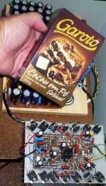
Everybody smile when listen this amplifier first time in my home
It is alike a good Chocolate cake...inside cream and coconut...everybody smile to the cake, the same when they listen the DHR Turbo.
"Dx High Resolution Turbo, a delicious amplifier!"
* Corporation Marketing Division, advertising number 0-34A32Z
hehehe
Carlos
It is alike a good Chocolate cake...inside cream and coconut...everybody smile to the cake, the same when they listen the DHR Turbo.
"Dx High Resolution Turbo, a delicious amplifier!"
* Corporation Marketing Division, advertising number 0-34A32Z
hehehe
Carlos
Attachments
Hi dx,
i just completed the prototype circuit. it is now checking for any things left soldard or error. tomorrow i will power on it.
good night for now.
best regards
michael
i just completed the prototype circuit. it is now checking for any things left soldard or error. tomorrow i will power on it.
good night for now.
best regards
michael
Good..... give a triple check into transistor position
Check if NPN is into the NPN position and PNP into the correct PNP position.
Check the electrolitic condenser values and polarities.
Check the diodes, the bias diodes, for polarity and shorts against the heatsink.
Measure the resistances to be sure you have the correct value..into the circuit they will measure less than the correct value, but will never measure more than the correct value.
Check zener polarity, check if you are using a 16 volts zener.
Check resistances from plus to ground, from plus to minus and from minus to ground.... and then invert your multimeter probe points, measuring resistances...more than 20K must appear into all readings.
Check board for shorts and open circuits.... paint into your schematic previously printed, the interconnection lines...the copper lines into your board or wiring... and paint red (or other colour) the lines checked.
Check your supply voltage and polarity.
Bias trimpot (220 ohms or 200 ohms unit) adjusted to 100 ohms
Off set trimpot (100 ohms unit) adjusted to 75 ohms into the first try.
After all adjustments, check voltage over the emitter resistances you have into the power transistors, into the output... reduce to less than 1 miliampere to each transistor.... 1 milivolt will be the reading there.
The amplifier works fine, it is still playing all day long here...many hours into test and stable... operating cold and sounding great...be sure it works if you follow the schematic... relax...the amplifier was tested...guaranteed!
Smile and be happy, you will listen a very nice sound.
regards,
Carlos
hooor.....re.....i sucess to make...DX- turbo
Dear carlos,
yes, first shot i was sucess to listen. though i am running into low voltage now about 24v but it is only for starting. sound is really wonderful, i can't believe. much much btr then Dx-prc-1....clean too. i am just added only one pair of transistor. i even't use sanken yet...i just used 2sc5200, wow....so clean....really nice....wonderfull...
it is more then worthy to place on my space heatsink.....ha...h.a.....
now i will check all details for final making.
let me check even more farther.
this information only to let you know that it is working ...nice.........................
kisses on you chick......ha...
best regard...
michael
update
information.
it is running very cold. heat sink dosn't get much hot. my amb temp is now 28c (because raining), heat sink after run 1 hr is just 32c, i just added two pair transistor at output and votage incresed to 30vdc 5 amp. my heat sink is small size, it is only 10inch X 4inch. there are 24 fins.
Few questions:
1: without input connection, how much voltage should be at output?
2: what is the output transistor E-B voltage should be?
so far no problem at power on and off time. this is a very cold type amp. not like prc-1. listen the sound quality first...
Thank you
michael
update PCB
....no time , but the latest PCB (driver ) http://i32.tinypic.com/28a3new.jpg and final stage http://i26.tinypic.com/21kfivm.jpg 😀 all the best alex mm
....no time , but the latest PCB (driver ) http://i32.tinypic.com/28a3new.jpg and final stage http://i26.tinypic.com/21kfivm.jpg 😀 all the best alex mm
Great news Space.... sounds beautifull.... i do feel the same when i listen to it
Sounding even better than the Precision I
The output can measure from 1 to 25 milivolts...and this will depend to the use of correct voltages and matched components, in special the differential pair.... you have adjustment into the differential, the 100 ohms trimpot....but... using very low voltage you may find different results.
People loves to test amplifier with half voltage...in your personal sittuation the voltage is even smaller.... well..... i think it is more interesting to use the correct voltage and protective resistances.
My prototype has 14 milivolts.... i have not adjusted....i found fine this way... the bias was adjusted and when checking the off set i found this voltage and i left it the way it is...no problems with some milivolts there... this means 24 microwatts (0.000024W) .... do not move speaker and do not produce audible noise.... means half of nothing...but the trimpot can make it zero.... my transistors had 20 percent gain difference.
Worries about very small off set voltages is "academic hot air"... but more than 25 milivolts is considered too much by many factories, they suggest us to adjust to obtain less than that... i really do not know why...maybe fashion.... the need of precision...do not know what moves people to worry with some details alike that...maybe my deep awfull ignorance....well.... everyday learning something... i hope some academic comes to explain us that it is not "academic hot air"... the provocation is here... already posted..hehehehhehe.
regards,
Carlos
Beautifull Alexandru.... dear Alex mm.... very good
Now it is more and more close to the perfection....ahahaha...be carefull not to turn sick or obsessive with that...it is good enougth.
To my taste it has a defect...something i do not like.
The numbers, the letters, are too much big... seems too much advertising..... i hope you can reduce letters size and make them ALL, the same size.... even my name, your name, the board dimensions...make those things smaller, please.
Very good work.... yep... i can survive with those big letters, as this is not for sale.... is a diy product...but i really do not like big letters, seems crowdy..confused and too much "propaganda"..too much advertising.
I feel when we have small letters silk screen, the amplifier have more class, more elegance, more beauty, more charm.
Thank you very much by your competent work.
regards,
Carlos
Dx Amplifier... the one had boards made into the Independence day
Star and stripes to you folks!
hehehe
Carlos
Star and stripes to you folks!
hehehe
Carlos
With this small voltage you will not feel any heat.
In special with bias adjustment made correct, it will be an ice box...very cold with this voltage.
I really do not like heat into transistors.... when you hold them between your fingers and do a gain test you will see what happens... they are too much sensitive to heat.... i use to keep them as cool as possible.... good heat to me is NO heat.
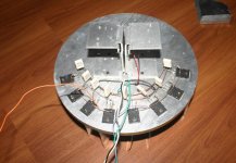
The heat sensor diodes i have used were the same output transistors... i have used the NPN devices... four of them, spread into the heatsink flat surface.... 2 into one extreme and 2 into the other.... them i have runned wires into them.
The use of the same transistors worked great.. they have the same thermal track compared to the output...because they are the same....so... when the output turns hot and internal resistance is reduced..the same happens into those transistor used as diodes...their internall resistance will reduce into the same ammount... worked fine!
The transistors i am using is 2SC3284..... i have receive a lot ...maybe 40 or 50 from Dudainc.... from Washington...now i am very rich, and as i use to produce prototypes and dismount prototypes, i have much more than i need for prototyping work.
This same transistors may be used into other idea... i use to assemble and test... the unit stays assembled by some time and the parts are used in another idea..... well.... this is changing slowly...now a days i have a lot of things keept assembled...i am turning very wealthy related parts in my home.... thanks to Duda.
My unit, the prototype plays all day.... the transformer goes hot...but i cannot feel heat into my amplifier...it stays alike the environment temperature...around 26 degrées celsius..plays low volume... all day long at least than 1 watt.... background music...ambience music only.
regards,
Carlos
In special with bias adjustment made correct, it will be an ice box...very cold with this voltage.
I really do not like heat into transistors.... when you hold them between your fingers and do a gain test you will see what happens... they are too much sensitive to heat.... i use to keep them as cool as possible.... good heat to me is NO heat.
The heat sensor diodes i have used were the same output transistors... i have used the NPN devices... four of them, spread into the heatsink flat surface.... 2 into one extreme and 2 into the other.... them i have runned wires into them.
The use of the same transistors worked great.. they have the same thermal track compared to the output...because they are the same....so... when the output turns hot and internal resistance is reduced..the same happens into those transistor used as diodes...their internall resistance will reduce into the same ammount... worked fine!
The transistors i am using is 2SC3284..... i have receive a lot ...maybe 40 or 50 from Dudainc.... from Washington...now i am very rich, and as i use to produce prototypes and dismount prototypes, i have much more than i need for prototyping work.
This same transistors may be used into other idea... i use to assemble and test... the unit stays assembled by some time and the parts are used in another idea..... well.... this is changing slowly...now a days i have a lot of things keept assembled...i am turning very wealthy related parts in my home.... thanks to Duda.
My unit, the prototype plays all day.... the transformer goes hot...but i cannot feel heat into my amplifier...it stays alike the environment temperature...around 26 degrées celsius..plays low volume... all day long at least than 1 watt.... background music...ambience music only.
regards,
Carlos
Attachments
update
dear dx,
i just added two more pair of transistors so total now 4 pair. i got a bit problem now E-b at output transistors voltage get abnormal up down like suddenly above 0.600v then when i touch the diod for a while its comes down to 0.150 where it suppose to be.
now question is, i haven't fix the diod board on the heat yet. dose it cause by diod? last time when i was playing with only two pair of transistor its dosn't hpns even i never attach diod on the heat sink.
i am now attaching on my space heat sink...i will show you the pic.....soon....ok...wait..
best regards.
michael
best regards.
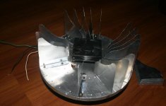
heat sink finishing with heat compound and DX-turbo.
dear dx,
here is the picture DX-turbo......space heat sink.
you can see back side placed transistor for one channel and another side unfinished fins assembled. i was assembling the fins with heat compound.
thanks for view.
mchael
dear dx,
here is the picture DX-turbo......space heat sink.
you can see back side placed transistor for one channel and another side unfinished fins assembled. i was assembling the fins with heat compound.
thanks for view.
mchael
Attachments
Use that condenser, the 2,2uf that is connected into the diode series
Also check if your zobel is connected.... check if into the output you have some AC voltage (oscilation)...if positive, then increase the miller capacitor...that one you have into the VAS transistor, from base to colector..... if no result, then increase the feedback condenser to 27pf (from 10pf to 27pf).
Have you grounded your heatsink...do that first..in advance.
Seems to me, dear Space, as you are made of liquid...we humans have a lot of liquid... and your size...your are an antenna tunning signals...your finger is injecting or removing (grounding) signals.
Nice that...hehehhehe...very nice.
Keep me informed...maybe the "ionized field around the space ship..ahahahahahah!"
Interesting.
regards,
Carlos
The DHR is so huge, so powerfull, because inspired into some ancestor i had from
Holland..... i use to call that spiritual influence as something that came from Baron Melter Von Kaput.... no speaker will survive if you open the volume all way up!
Of course... square wave, from any amplifier has a lot of harmonics and the power on it..the average power, is almost continuous DC power into the speaker.... every powerfull amplifier can do that...having big supply power...not only DHR.
But advertising is advertising.... DHR is strong..others melt the speaker..heheheh
regards,
Carlos
Attachments

This was my real ancestor...he was the first brazilian son from Holland people
6 generations ago, into my mother line family.
This was was in Brazilian Army.... furriel after finished the Empire we had long time ago.... Dom Pedro de Orleans e Bragança was the Emperor those early days... and then we enter Republic of the United States of Brasil.... a federation of States alike USA.
regards,
Carlos
Attachments

I would like to remember you dear Space...that we are aerials, antennas
When you put your finger into the amplifier input..you gonna have 60 hertz mains frequency, your body captured from house wiring and your finger is the probe tip point of a 60 hertz sound injector into the circuit...you are the generator, the sound source, because your body has the Antenna characteristic.... Aerial.
No only metalic bodies are transducer...we have metal inside..we have also watter.... our body can capture, attenuate some frequencies and detect in a wonderfull way others.
When the house wiring is powered, and when you have consumption of energy crossing those wires... travelling into those wires, a lot of electromagnetic energy is irradiated, transmitted into the air... and you can capture as an antenna.
Also VHF broadcastings (powerfull) and AM broadcastings, also Cel phones and TV broadcasting are captured....so...fingers into electronic parts...ahahahahha..in special diodes that removes the RF and let the modulation go ahead...is annoying thing to electronic devices, amplifiers shows this clear, as create unstabilities.
The cure is to "remove the finger"...ahahahahha... find another place to put your finger rigth?
hehehhehe....not that place!....not in me too"
regards,
Carlos
zobel.
dear dx, i think R16 is the zoble right? i attached the diagram for you. i am following this diagram. it is a bit diffrent then you posted here. i got it from your web site.
if it is not zobel, then which value should is use? 10ohms in series with 100nf cap to the GND?
sould i attach the diod on to the heat sink. i have some spare 2sc5200 and 2sa1943.
thanks.
Attachments
Well man...your are behaving as a bad boy to uncle Charlie and will not receive
Chocolate bar this holiday...hummmm...bad boy not reading things.... there's an updated, much better schematic...your are using the old schematic... already substituted by the revision 2.
Unfortunatelly Todd Johnson is very busy and could not make the official pretty schematic...but i have published the revision 2 in the thread...bad boy do not read....it is OK!.. at least you build things..use your time to build in the place to read...it is fine.
I will show you the modifications in several images (big work)
regards,
Carlos
Attachments

- Status
- Not open for further replies.
- Home
- Amplifiers
- Solid State
- This is the DHR.... Dx High Resolution Turbo