Re: Will give detail latter.
Working on it (albeit slowly). I'm also installing the hardwood floor this week so not much spare time. Home Depot loves me this week.
..Todd
destroyer X said:
Schematic is this one.... Todd may produce something decent near future.
He is the Director of Art works into the Corporation (hehehhe)
Working on it (albeit slowly). I'm also installing the hardwood floor this week so not much spare time. Home Depot loves me this week.
..Todd
Are you still using papper as heat insulating material inside walls?
I hope not.... mouses, mice, rats, loves papper.
Also sound is not good.... papper when dried is sonically reverberant...also wood is not good.
I am happy i am living into a brick, cement, concrete house... i would feel afraid to be inside wooden home (fire!)
My problem is the floor...made using ceramics... too much reflexive to treble... and aluminium window frames.... also vibrates into bass... i have here a 250 hertz ressonance... and i hate that frequency... it could be removed from the spectrum.
Do you use fiberglass and cotton as heat insulation, or that chemical foam that expands inside the wall (oh pain, this loves fire too!)
ahahahhah!
regards,
Carlos
Carlos,
Regarding the 270nF cap parallel to 2200uF... 270 value is a bit unusual. Can it be 330nF or 220nF? It would be easier to find those values.
..Todd
Regarding the 270nF cap parallel to 2200uF... 270 value is a bit unusual. Can it be 330nF or 220nF? It would be easier to find those values.
..Todd
Yes.. from 22n to 1uf.... the value you could find cheap, small and that can hold
twice the supply voltage...for sure you can use.... i think 100n is good...but for this purpose (the big throat to eat oscilations... the low impedance to send high frequencies to ground) every capacitor will work fine, as they represents very small internal resistances to high frequencies.
Anyone of those capacitors are used for tuning purposes or operates inside the audio chain, they are all auxiliary as by pass of electrolitic condenser internal inductance.... they are constructed, internally, alike a coil.
regards,
Carlos
Re: Are you still using papper as heat insulating material inside walls?
Paper? Nope. "rockwool" and/or "fiberglass" is the standard. I prefer rockwool as it is a GREAT acoustic absorber. But it doesn't help too much being inside the wall/floor. These are both fire proof (relatively speaking). Rockwool wins in that category too.
..Todd
destroyer X said:
I hope not.... mouses, mice, rats, loves papper.
Also sound is not good.... papper when dried is sonically reverberant...also wood is not good.
Carlos
Paper? Nope. "rockwool" and/or "fiberglass" is the standard. I prefer rockwool as it is a GREAT acoustic absorber. But it doesn't help too much being inside the wall/floor. These are both fire proof (relatively speaking). Rockwool wins in that category too.
..Todd
Thank you by the informations about thermal insulation inside home in Canada.
About the DHR, i am using those diodes as thermal sensor.
I have tried, also, NPN power transistors, the same i am using into the amplifier (2SC3284) and they have worked fine too...but, i have used insulator for safety reasons, and with this one insulator not needed, you have to screw it into the heatsink and connect them in series (4 units in series)
regards,
Carlos
Attachments
I have made some modification, but the informations previously posted
are usefull.... zener diode gonne to 16 volts.... some resistance values have changed, some capacitor have changed too, output coil included, 1 ohm resistances to the power transistor emitters, new value to the driver's emitter suckout capacitor, new value of preset resistance to bias trimpot (68 ohms).... 270 ohms in series with the bias trimpot, and those resistances in series are "over" the series of thermal diodes..connected into the extremes as you can see into the image.
Important... adjust the amplifier when cold....bias is informed into the image, and check milivolts DC over emitter resistances...and re-adjust your bias to read something around 500 microvolts (less than 1 milivolt please).... then adjust off set and check bias once again... if you had to readjust the bias, then check the off set once more...if not needed to readjust bias do not touch the off set trimpot anymore.
Adjust with the amplifier input shorted to ground... a good idea is to place some resistance into the output, into the speaker place, value from 4 ohms to 100 ohms during the adjustment.
Voltage from base to emitter into the input will be around 575 milivolts... into the VAS the voltage from base to emitter is around 630 to 650 milivolts... the drivers measure 540 milivolts and the output will measure 520 milivolts.
The output coil, 1 milimeters wire, 22 to 32 turns over a resistance... the internal resistance must have value bigger than 18 ohms...so, de diameter will be the resistance diameter, and this will be from 8 to 12 milimeters.
Resistances are 1/4 watt, exception into the output emitter resistances (1 ohm and 3 to 5 watts each one).
Install fuses into your amplifier, into the positive rail and into the negative rail and ALSO, into the output.... the rail current you can have the inform into a chart i have published some posts ago... use the more close fuse value you can have to the current readed without distortion.... use bigger, as the readings was without distortion.... into the ouput, twice the value of the rail fuses, as the current there will be positive rail plus negative rail currents into the load.
Use 1/2 watt to the boostrapp resistances.... 3K6 is the value of each one of them.
The boostrapp condenser must be a 100 volts unit... or even more for safety reasons.... the feedback condenser (220uf) must be 70 volts of more into the maximum operating voltage...input condenser can be 12 or 16 Volts standard electrolitic condensers.
The zobel resistance must be bigger, 1 watt will be good...and the zobel capacitor must be 150 volts or more into the insulating voltage.
Atention to insulation voltage into the condensers...now we are operating into 70 volts...so...bigger voltage condenser must be used.
The rectifier must be huge, and filter values were suggested into the chart.
regards,
Carlos
Attachments
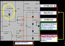
Atenttion please... some diodes i have tried shown different forward voltage drop
Those high speed black plastic ones have near 1 volts...so i found that i had to make modifications into the resistances working together the series of diodes (image).
Better to use standard plastic transistor packages, or, to use insulators into cheap TIP41 transistors or something alike... the best sittuation is to use the same transistors you are using into the output...the 2SC3284 transistors...maybe this is ask too much, as they are expensive...but they are working great together, as they have the same "thermal track" because they are the same used into the output...so... the more the hot output transistors increase the current (because characteristics change while hot), the transistors, the same ones, working as diodes, as heat sensors, will decrease the junction forward voltage into the same ammount you have into the output... and this will compensate the whole thing working great.
I was confused with that and i have asked things to Doctor Jan Dupont and to my dear friend Hugh Dean too.
So... the schematic values shows the correct value to standard diodes or standard forward voltage drop diodes...forward voltage of 600 milivolts or so..... and this one, despite nice to use, and working very well also, will need substitution of one resistance and another adjustment into the bias trimpot to 100 ohms.
regards,
Carlos
Attachments
The bias, the current into output devices are adjusted to less than 1 miliampere to
each one of the output transistors.... measure 1 milivolt over the 1 ohm emitter resistance...or less than that.
Install your DC milivoltimeter into the emitter resistance extremes, the red probe point goes to each one of the power transistor emitters (one each time) and the other probe point, the black probe point goes to the output line... this one stays fixed into the output line while you make your measurements.
Check all emitter resistances, they me be sligthly different but all them must read something small... 1 milivolt or less than that.
Measuring into the protective rail resistances, in this case use 20 ohms resistance in series with the rail voltages, and you may obtain from 600 to 700 milivolts... this means current to the positive side of the circuit from 30 to 35 miliamperes.. the full current consumption, the the whole circuit, into stand by condition...input shorted, and off set adjusted to lower value than 5 milivolts
regards,
Carlos
Time to make Turbo....
Dear DX,
i just made aleph-3, 30w. now assembling.
Time to get ready to make Turbo....DX........waiting for complete version of circuit diagram.
It will btr to write on the circuit diagram some components voltage should be, it will makes us more easy to find some human error problem. also will be easy to understand that the amp is operating well. as i follows aleph-3.....
Thank you for your contribution to use with nice design.
VRO Board again......ha.....and copper plate too. lots of copper plate...
best regards
michael
Already posted voltage informations into a schematic, current information and VBE
Post 19, 20, 21 and 22.
Adjustment information also published.
search in this same thread, the informations you want were posted.
regards.
Carlos
......................................................................................................
As output pairs, i am using 2SC3284 and 2SA1303.... also i am using those same transistors as drivers, working into driver position...the VAS you can use 2SC4793 or a lower capacitance unit you may find...power there is lower than 5 watts...so... every five watts transistor, 100 Megahertz unit, for audio purpose, that can accept voltage bigger than 150 volts willw work there...no magic mistery...just a transistor, not more than a transistor..without any magic eletrons.
As heat sensor, as diodes, i am using power transistors, the same 2SC3284 worked great..base to emitter junctions were used..they are compensating heat very well... every power transistor, TO220 or bigger will work fine..... you can try some plastic ones, more cheap units if you want.
Do not forget to search for the current chart published in this thread..it is small... so read it entirelly.... a good idea is to read more dear Space...you question, asking for voltage charts, proved me you do not read.
regards,
Carlos
Attachments
It is playing, all day long, a couple of days playing.
It is stable and sounding excelent.
here is the bias adjustment...make it with your amplifier cold, adjust the offset and then the bias... check the off set again and return to the last touch into the bias trimpot shown.
regards,
Carlos
It is stable and sounding excelent.
here is the bias adjustment...make it with your amplifier cold, adjust the offset and then the bias... check the off set again and return to the last touch into the bias trimpot shown.
regards,
Carlos
Attachments
Here you have the off set adjustment
This amplifier was tested full power for long time...heatskink was near 100 degrées celsius (was not measured, but too much hot to touch without burn fingers) when driven for long time clipping into a resistive and inductive dummy load.... the power was enormous, much more than the small heatsink i was using can hold.... so.... was tested under worst conditions... and survived!
Thermal control worked and have maintained the bias current stable and small, even while the amplifier was very hot.
So, it is reliable, tested, you can trust and evaluate sonics by yourself.
Made for heavy duty, for Brazilian powerholic folks... to work using 70 volts maximum...to drive 4 ohms or lower impedance loads and to play maximum undistorted power and to survive playing distorted power too...working on clipping, when you have much more current and stress to output transistors.
regards,
Carlos
Attachments
We have no board at this moment for this upgraded, modified model
So, you have to produce your own board.
regards,
Carlos
So, you have to produce your own board.
regards,
Carlos
PCB upgraded ......still mising until next weak
Sorry folks , I'm busy right now with , wedding of my son .Next weak I will try to do a nice PCB , until then patience .....🙂
regards alex mm 😀
Sorry folks , I'm busy right now with , wedding of my son .Next weak I will try to do a nice PCB , until then patience .....🙂
regards alex mm 😀
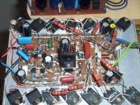
The prototype is very ugly....but it is sounding great!
The best sound amplifier i have ever made.
This is the final amplifier, will not make anyone amplifier more.
Maybe some modifications to increase or decrease power, but substantially, the amplifier will remain the way it is now a days.
I will continue researching, curiosity is something i have...but i do not believe i will find something much better than this one.
I am listening some details i have never listened and i am surprised those sound details were recorded previously and i could not listen with so many models i use to test here.
In the future....my dream of a Corporation, i will give money back to the one bring to me better sound device and let me test it with several people, common people, selected into the street.... a double blind testing.
regards,
Carlos
Attachments
I change my mind ......PCB rev 2
... I'ts too long time until next weak , and folks have no patience ,so here you can find an option for PCB 😀 http://i27.tinypic.com/j0i809.jpg please find errors to make the right one .Regards alex mm .
... I'ts too long time until next weak , and folks have no patience ,so here you can find an option for PCB 😀 http://i27.tinypic.com/j0i809.jpg please find errors to make the right one .Regards alex mm .
- Status
- Not open for further replies.
- Home
- Amplifiers
- Solid State
- This is the DHR.... Dx High Resolution Turbo