Thank you Viktor, also thank you Alex mm
I will follow your link Alex and will observe, in details your board.
regards,
Carlos
I will follow your link Alex and will observe, in details your board.
regards,
Carlos
Viktor....this amplifier is sounding great!
Will be very difficult to find someone that will not like this sound.
It is very flat...very ballanced...not too much bass...but it is tigth, controled, undistorted, very clean, deep and real.
Also voices and treble... this amplifier is excelent..guaranteed!
Goes from 0.5 hertz to 180 Kilohertz without losses and without deformation into the sinusoidal tone that enters the circuit.
Dinamic is great...the bias point is very low..so you have room to increase current into the output without saturate too much soon.
Noise is almost none...or half as none... you can put your ears into tweeters and hard to listen thermical electronic noises.
Flat.... really playing flat.... no preferences for bass, voices or treble..this one is really flat...not flat into measurement...this one SOUNDS flat!
regards,
Carlos
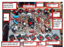
Alex mm this new revision 2 version, the last and final
Is using 5 pairs of output power transistors, and, in my boards i am using the same ouput pair into the driver position...yes..power transistors working as drivers.
In this case...a good idea is to place drivers into the main heatsinks... this will "look" alike we have 6 pairs.... we gonna have 6 pairs, but only 5 pairs into the output...the extra pair will be drivers.
Do not install the VAS into the heatsink...keep this one into the board please.
regards,
Carlos
Attachments
DHR, this amplifier is the one i love the most
From Dx Corporation, South American Laboratories to your home.
Entirelly for free.
Satisfation guaranteed!
regards,
Carlos
From Dx Corporation, South American Laboratories to your home.
Entirelly for free.
Satisfation guaranteed!
regards,
Carlos
DHR PCB re...revised
... Driver PCB revised http://i25.tinypic.com/2z4wfgx.jpg and final stage PCB http://i27.tinypic.com/rjgv2o.jpg , with 5 pairs this time 😀 . All the best alex mm😉
... Driver PCB revised http://i25.tinypic.com/2z4wfgx.jpg and final stage PCB http://i27.tinypic.com/rjgv2o.jpg , with 5 pairs this time 😀 . All the best alex mm😉

Duda, this is special for you... about the last image posted
I use to comment that we have to plug our audio sources directly into the amplifier.
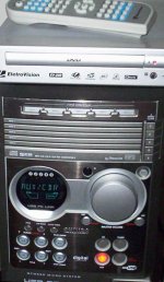
Man... i use to listen from the Class D system...because it is almost entirelly digital..has only a single chip to the headphone...so, i am using this headphone output... sounds excelent.
Now a have tried a DVD, this one has good sound when playing DVDs... also when playing MP3.. this one plays everything, all codes.
But it is entering the Philips System auxiliary input..... man... having the Philips into the audio chain killed the sonics entirelly, the audio became so poor that i am searching for the double barreled to give a shot in this dam thing.
Even this amplifier, the one sounds great, having something in the middle of the audio chain can kill the sound quality.... almost everything but potentiometers can kill the sound... even wrong value potentiometer into the amplifier input....it must be bigger than the input impedance.... not to match perfectly the audio source, not to match perfectly the power amplifier input but not to "load" anyone of them.
Nothing into the power amplifier input...only audio cable and conectors.... of course, sometimes we cannot avoid volume control, BUT, if the audio source can control level..better not to install even potenciometers... short connection helps a lot too.
regards,
Carlos
I use to comment that we have to plug our audio sources directly into the amplifier.
Man... i use to listen from the Class D system...because it is almost entirelly digital..has only a single chip to the headphone...so, i am using this headphone output... sounds excelent.
Now a have tried a DVD, this one has good sound when playing DVDs... also when playing MP3.. this one plays everything, all codes.
But it is entering the Philips System auxiliary input..... man... having the Philips into the audio chain killed the sonics entirelly, the audio became so poor that i am searching for the double barreled to give a shot in this dam thing.
Even this amplifier, the one sounds great, having something in the middle of the audio chain can kill the sound quality.... almost everything but potentiometers can kill the sound... even wrong value potentiometer into the amplifier input....it must be bigger than the input impedance.... not to match perfectly the audio source, not to match perfectly the power amplifier input but not to "load" anyone of them.
Nothing into the power amplifier input...only audio cable and conectors.... of course, sometimes we cannot avoid volume control, BUT, if the audio source can control level..better not to install even potenciometers... short connection helps a lot too.
regards,
Carlos
Re: Duda, this is special for you... about the last image posted
Carlos,
If your DVD player gives you control of the line output, then I would connect it directly to your amplifier input (after confirming you do not have an impedance mismatch).
Yes you will loose tone control, etc., but you will be better off this way.
The bottom line is: get away from that "plastic monster"... Plastizilla? 😀
Originally posted by destroyer X
...
But it is entering the Philips System auxiliary input..... man... having the Philips into the audio chain killed the sonics entirelly, the audio became so poor that i am searching for the double barreled to give a shot in this dam thing.
...
Carlos,
If your DVD player gives you control of the line output, then I would connect it directly to your amplifier input (after confirming you do not have an impedance mismatch).
Yes you will loose tone control, etc., but you will be better off this way.
The bottom line is: get away from that "plastic monster"... Plastizilla? 😀
Yep... will plug directly.... i will proceed the remotion of this plastzila
The Plastic Godzilla.
Sounds fine this Philips...hehe..no sound stage, no audio band extremes (losses), but huge power, nice sound...we can survive in a pleasant way listening to it...but cannot compare!... if you try that will give a shot on it!
regards,
Carlos
The Plastic Godzilla.
Sounds fine this Philips...hehe..no sound stage, no audio band extremes (losses), but huge power, nice sound...we can survive in a pleasant way listening to it...but cannot compare!... if you try that will give a shot on it!
regards,
Carlos
Dear dx,
Today i will be buying all the parts to make fantastic Turbo DX.....XXX amp. using that giant heat sink.....oh...ho....first i will be using one pc of heat sink. i am not shure that one can put two channel or not. if need another one i already bought the plate and sheet for one more pc, as i sucess to make one so can can make few even. first, i will try on it see the temp how is going.
At first i will make protype board just to see the working condition. then i will make final one as i did last time. i will let you know about every progress i made.
probably i will need your assistance sometimes. thanks for your great help.
best regards
michael
need assistence
dear dx,
i am following dx-turbo diagram that u have uploaded on your dx website.
i have attached that diagram.
i am confused about R18 and R22 this two should be same value but here showing is dfrent. R18 is 100ohms and R22 is 180ohms which should i follow?
thank you
micahel
dear dx,
i am following dx-turbo diagram that u have uploaded on your dx website.
i have attached that diagram.
i am confused about R18 and R22 this two should be same value but here showing is dfrent. R18 is 100ohms and R22 is 180ohms which should i follow?
thank you
micahel
Attachments
I have reduced those resistances value to obtain maximum power, to reduce losses
And...because of that, the left side electrolitic condenser is bigger than the last schematic.
In the reality, both sittuations will work fine...the last schematic was posted, in pdf, but not that pretty schematic...this is the version one that is beeing fixed by Todd Johnson... some details are beeing corrected....but do not worry, both versions works fine... they were tested... the last revision, revision 2, gives you sligth advantage in power compared to the first schematic....Maybe i have forgot to tell Todd that i have reduced the rail resistances value... will check that.
This amplifier was made with the main focus on power...quality was secondary in my mind..... was unbeliavable to me that quality resulted so good this way.... i have to say this was entirelly unexpected.... a very good surprise.
I always try my best to tune to audio quality...had not too much hopes on this one... was a nice surprise could beat the Precision 1 in quality.
This amplifier depends, alike everyone, into the transformer power, the electrolitic condenser capacitances, the small resistance of wiring (we have huge current).... depends on stable voltage from the supply (huge transformers) and good selection of parts (non fake parts)
There are no golden parts, no stripped condensers, no wonder parts.... the miller capacitor, will be better to be silver mica...but ceramic will work too...not so great..but will work also.
The input are normal, standard, cheap, common, regular, electrolitic condensers, 16 volts units... 10uf each one.
Good luck...final pretty schematic soon.
You have my last PDF published with schematic...in this same thread...go back and search for it please.
regards,
Carlos
Here you have, dear Space, some informs
Those informations were sent to Todd Johnson too.
I am using normal output transistors..the power ones, as diodes...i found interesting as they can capture heat in a better way than diodes...they can be fixed using screws and using insulators will be better... they have the same heat tracking than the ouput... beeing the same, they will have same ammount of resistance drop.
Also, i am using the same output transistors as drivers....because the same reason.....but... 2SC4793 nd 2SA1837 will work fine too.
You see...bias is small.... around 35 miliamperes into the positive rail...means 350 milivolts measured over 10 ohms protective resistances.
But i strongly suggest you to measure the voltage drop over the emitter resistances, and adjust those ones to less than 1 milivolt... and this will means you will have less than 1 miliampere crossing.
The amplifier is beeing made to hard use...heavy duty...to me a destroyer, a smasher, a killer, a thunderstorm, an earthquake, a competition's nightmare...very huge power...a monster...keep it cool .... adjust the stand by current and check the current drop ove the emitter resistances....this adjustment is very, very, important..this amplifier will send to speaker, or speakers a big ammount of current... alike an electrical solder machine it is a monster!... check current over emitter resistances..and adjust to have resistance there low.
I am using BC556 and BC546 into the prototype...SO... they are good enought..if you prefer, go to 2NXXXX.... high voltage types if you want...no problem...gain must be from 100 to 350...the bigger, the better..and they must be matched...PNP matched with PNP and NPN matched with NPN ( matched in gain..inside 20 percent tollerances)
To the VAS i am using 2SC4793...and it is working great together 39pf of compensation (use Silver Mica to this one)
regards,
Carlos
Attachments
Here is the schematic...i have copied from the prototype
This is something very guaranteed..the values are the ones into the board made, the one is working, playing music those last days
A real amplifier, not a simulator thing...this is real!... not a virtual amplifier that may work fine..this one is working, playing!...a several days playing!...and ... G-R-E-A-T!!!
regards,
Carlos
Attachments
- Status
- Not open for further replies.
- Home
- Amplifiers
- Solid State
- This is the DHR.... Dx High Resolution Turbo