fedde said:Putting the + input of the opamp directly on the power ground is asking for problems. Please follow the recommendations of me or Thorsten for proper grounding. (separate signal ground star and power ground star).
Fedde
Or even better, as he recommended me (nice guy😎 ), put a 50k multi-turn pot in place of that resistor.
Then you can easily adjust DC Offset to 0 mv, as I did.

Bricolo said:what about using IC regulators (5A, maybe 10A) to filter the PS lines?
Yes, that's it.
Anybody tested this with a Gainglone?
I had already asked, but nobody repplied.

Bricolo, join me in the "stabilized-PSU-is-almost-as-good-as-batteries" brigade.


carlosfm said:
Yes, that's it.
Anybody tested this with a Gainglone?
I had already asked, but nobody repplied.
Bricolo, join me in the "stabilized-PSU-is-almost-as-good-as-batteries" brigade.
Several people have tried and I think Fred was the first one to mention it and also the first one to mention it again that it had been tried.
fedde said:Putting the + input of the opamp directly on the power ground is asking for problems. Please follow the recommendations of me or Thorsten for proper grounding. (separate signal ground star and power ground star).
Fedde
a link?
carlosfm said:
Or even better, as he recommended me (nice guy😎 ), put a 50k multi-turn pot in place of that resistor.
Then you can easily adjust DC Offset to 0 mv, as I did.
in the place of which resistor?
Let there be sound
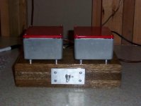
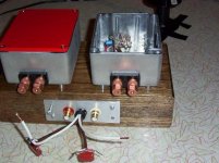
I just finished both channels of my amp. I used the schematic as posted on the amp chip forum. I left out the .22 Ohm resistor at the output. I don't have my power supply finished so what I am using in the meantime is two 12 volt 3A AC-DC convertors in serial with ground centered in between. I don't know why people bash the bass. Even with this setup the bass is quite well controlled although it falls apart higher demands. I suppose that once I get a decent power supply made (battery) things will improve subtantially. The mids and highs are very clear and neutral. My speakers are homemade Audax two-ways which are neutral. Sorry, no pics yet but I will post some ASAP. Overall, I must say that I am quite pleased.
I just finished both channels of my amp. I used the schematic as posted on the amp chip forum. I left out the .22 Ohm resistor at the output. I don't have my power supply finished so what I am using in the meantime is two 12 volt 3A AC-DC convertors in serial with ground centered in between. I don't know why people bash the bass. Even with this setup the bass is quite well controlled although it falls apart higher demands. I suppose that once I get a decent power supply made (battery) things will improve subtantially. The mids and highs are very clear and neutral. My speakers are homemade Audax two-ways which are neutral. Sorry, no pics yet but I will post some ASAP. Overall, I must say that I am quite pleased.
Re: Let there be sound
This is a general pledge to those who have made nice cases*: please mention something about how you dit it, if there was any unusual techniqes/methods involved, please share!
* As for you vic, we'll see from the pictures whether you are included in that group 😉
vic said:Sorry, no pics yet but I will post some ASAP. Overall, I must say that I am quite pleased.
This is a general pledge to those who have made nice cases*: please mention something about how you dit it, if there was any unusual techniqes/methods involved, please share!
* As for you vic, we'll see from the pictures whether you are included in that group 😉
Matttcattt said:
a link?
Well, my pages are still on www.fedde.tk
More precisely, this page is the one I am referring to:
http://home.student.utwente.nl/f.s.bouwman/audio/diy-thor-amp.html
And a quote...
"The grounding layout is important in order to prevent hum and to reduce the noise of the amplifier. It is a good idea to have two star ground points per channel. One for low power signals (the ground for the input, the ground from the potmeter, the ground to the resistor and capacitor at the + input) and one for high power signals (the ground of the speaker, the two ground cables from the bridges and the 1000 uF supply capacitors). These two start ground points have to be connected. There should be no ground loops! I did not connect the grounds of the two channels, they are connected only in the DAC."
I want to add that these star grounds should be far from each other. This is from recent experience. Especially when the +input of the opamp is directly connected to the ground, correct wiring is ESSENTIAL. I always had some problems at high volumes, the sound got somewhat wooly. This was due to the +input connected closely to the power ground point. There are very large currents there, and the inputs of an opamp are very sensitive.
Now I have a wire from the + input to the ground of the input connector. The sound is much tighter this way! I will soon try to shorten that wire and connect it to the ground of the potmeter (stepped att.). This could even be better.
Good luck with your wiring,
Fedde
Re: grounding problem
Then is it only one channel or two channels now? 😉
OK, as fedde already pointed out, you have your input grounds connected to the power ground which might cause this. Other than that, I don't see anything wrong. Realization can be different though and we haven't seen a picture yet.
So, to sum it up about proper grounding, let me put it this way.
- Form a low level (others call it signal or input) ground point and connect the input connector outer ring (hopefully it's insulated), the bottom of the pot, and the + input of the opamp (or the bottom of the resistor/trimpot if you use one here to null out output DC offset). Also the bottom of the resistor if you use one between the - opamp input and the ground. Use thin wires here on making connections to this ground point.
- Form another ground point, let me call this one high level (or power, or output, or ...) ground point. Connect the two 0 leads running from the psu, one side of your speaker connector, and the appropriate legs of the 1000uF filter caps. Use wires of greater diameter here.
- Now tie up the two ground points with a thin wire and you're done.
Easier to make it than describing ;-)
Betcha got rid of that cutoff noiz, huh?
monguz
George Kubitsch said:
I have modified the original schematic a little , it is only one channel. V+, V- are +- 32V.
The sharp sound, oscillation is the same on both channels.
Then is it only one channel or two channels now? 😉
OK, as fedde already pointed out, you have your input grounds connected to the power ground which might cause this. Other than that, I don't see anything wrong. Realization can be different though and we haven't seen a picture yet.
So, to sum it up about proper grounding, let me put it this way.
- Form a low level (others call it signal or input) ground point and connect the input connector outer ring (hopefully it's insulated), the bottom of the pot, and the + input of the opamp (or the bottom of the resistor/trimpot if you use one here to null out output DC offset). Also the bottom of the resistor if you use one between the - opamp input and the ground. Use thin wires here on making connections to this ground point.
- Form another ground point, let me call this one high level (or power, or output, or ...) ground point. Connect the two 0 leads running from the psu, one side of your speaker connector, and the appropriate legs of the 1000uF filter caps. Use wires of greater diameter here.
- Now tie up the two ground points with a thin wire and you're done.
Easier to make it than describing ;-)
Betcha got rid of that cutoff noiz, huh?
monguz
UrSv said:
Several people have tried and I think Fred was the first one to mention it and also the first one to mention it again that it had been tried.
I remember that Fred has tested this, but I can't find his post anymore :/
carlosfm: I'll try it first, before becoming an addict 😀
grounding problem
Hi Peter, Fedde, Carlos, Monguz
Thanks for your replies, I will follow your proposal exactly , hope
it will solve my power off oscillation problem.
PS
I have two channels and both of them behave the same way.
George
Hi Peter, Fedde, Carlos, Monguz
Thanks for your replies, I will follow your proposal exactly , hope
it will solve my power off oscillation problem.
PS
I have two channels and both of them behave the same way.
George
The resistor
In place of the resistor that's between the non-inverting input to ground.
In the original Thorsten schematic it was a 220 kohm resistor and a 0.1uf cap.
He now recommends a 18 kohm resistor.
But better still, as he also recommends, is a 50k multi-turn pot.
Matttcattt, take it easy with your car amp, will you?😎
Matttcattt said:
in the place of which resistor?
In place of the resistor that's between the non-inverting input to ground.
In the original Thorsten schematic it was a 220 kohm resistor and a 0.1uf cap.
He now recommends a 18 kohm resistor.
But better still, as he also recommends, is a 50k multi-turn pot.
Matttcattt, take it easy with your car amp, will you?😎
This is a general pledge to those who have made nice cases*: please mention something about how you dit it, if there was any unusual techniqes/methods involved, please share!
Your wish is my command. Please click HERE .
Re: The resistor
ill try that.carlosfm said:
In place of the resistor that's between the non-inverting input to ground.
In the original Thorsten schematic it was a 220 kohm resistor and a 0.1uf cap.
He now recommends a 18 kohm resistor.
But better still, as he also recommends, is a 50k multi-turn pot.
ok, lol 😀
Matttcattt, take it easy with your car amp, will you?😎
I hope to have some pics available soon. As soon as I get a digital camera, that is. I hope to be able to join the elite gaincloners.
- Status
- Not open for further replies.
- Home
- Amplifiers
- Chip Amps
- This is not just another gainclone