They chosen like that because Riken isn't available in less than 0.5W, but if you use different type choose the Wattage that fits best between the pins of the chip (between - input and output). 0.5W is actually a bit too long. 1/8W Holco might be a good alternative.
I was advised by somebody in the hi-fi industry to try and use higher wattage resistors for feedback duty.
A good method with chip amps is to use two resistors in parallel so that they fit between the pins but provide a higher wattage rating. That's what I did with my Gainclones, using two Welwyn RC55's in parallel and they fitted between the pins perfectly.
Nuuk, what was the reason given for this recommendationNuuk said:
I was advised by somebody in the hi-fi industry to try and use higher wattage resistors for feedback duty.

/U.
gianclone schematic
Dear Peter,
I appreciate your experience, and would like to start building gianclone from your schematic as reference point. Please do not reefer to some post because I am little bit lost in all those infos and various schematic around the web. Please post (or send mail) of your schematic of that amp with heat pipes.
Thank you,
Ticovski
Check posts #882 and #883
http://www.diyaudio.com/forums/showthread.php?s=&threadid=9112&perpage=15&pagenumber=59
Riken 0.5W, 220k is better than Holco for feedback.
http://www.diyaudio.com/forums/showthread.php?s=&threadid=9112&perpage=15&pagenumber=59
Riken 0.5W, 220k is better than Holco for feedback.
I was advised by somebody in the hi-fi industry to try and use higher wattage resistors for feedback duty.
Nuuk, what was the reason given for this recommendation
Basically, for better thermal stability and lower noise.
Borc said:Is the PS wiring in picture in #882 for GND and -V, O.K.??
I've been thinking same. I think lower diodes d5-d8 need to be connected differently.
+ of d5-d8 should be connected to - of d1-d4 bridge and forms gnd.
- of d5-d8 connected to V-
Maarten
Nuuk said:
Basically, for better thermal stability and lower noise.
but with the added problems of a larger tollerance, greater effect of temprature on resistace and finding the right values of resistor
personally i would look into using large wattage reasistors that are the same size. such at some BC reistors which are rated at 0.6W in a 0.25W case
Borc said:Is the PS wiring in picture in #882 for GND and -V, O.K.??
I'm sorry, it's indeed not correct. The correct drawing is in post #889
http://www.diyaudio.com/forums/showthread.php?s=&threadid=9112&perpage=15&pagenumber=60
but with the added problems of a larger tollerance, greater effect of temprature on resistace and finding the right values of resistor
I don't think that doubling a 0.1% 15ppm tolerance is a problem and the thermal stabiility is increased not decreased isn't it
For the sort of quality resistors that should be used in this part of an amp circuit, and with the advantage of using two values instead of one, there isn't much of a problem in finding the right value.
help needed
Hi all!
After my OTL monobloks I have made my minimalized Gainclone
a la Peter Daniel. Four transformer, hexfreds....
The sound is very promising, will it be better over the time?
I have one problem which I could not solved yet:
When the amplifier is powered off , there is a short hurting sound
from the speakers. I looked at it on my scope and there is an oscillation on the outputs for some milliseconds.
The amplitude is not limited (about +- 30v), but at this time the +- voltages were floating (not earthed). With 100 ohms to earth the amplitude decreased to some volts, but it is disturbing also.
I tried zoebel on the output, 22k, 18k grounding resistors on the inputs no result.
If anybody could help
thanks
George
A picture would be helpful. You might have grounding problem, as there shouldn't be any sound when powering off.
what is the approx. max power rating of the OPA541 at +/-12v and +/-40v?
and at max volume, what is the approx. heat output in watts?
and at max volume, what is the approx. heat output in watts?
Re: help needed
George,
Four transformers, so probably you already built it stereo. Let me ask you first if this is sorta symmetrical for both sides. I mean if your GC is misbehaving the same way both on the left and the right channels.
PD was right, a photo and/or an detailed schematic would greatly help tracking it down. Just a hint: in case your transformers are center tapped, try temporarily feeding one channel with only one of them. Make your ps simpler for a try. But forget if it only has single sec. winding of course.
Could you attach the exact circuit of your ps? How the + and - sides are tied, particularly ground leads...
monguz
George Kubitsch said:
After my OTL monobloks I have made my minimalized Gainclone
a la Peter Daniel. Four transformer, hexfreds....
I have one problem which I could not solved yet:
When the amplifier is powered off , there is a short hurting sound
from the speakers.
George,
Four transformers, so probably you already built it stereo. Let me ask you first if this is sorta symmetrical for both sides. I mean if your GC is misbehaving the same way both on the left and the right channels.
PD was right, a photo and/or an detailed schematic would greatly help tracking it down. Just a hint: in case your transformers are center tapped, try temporarily feeding one channel with only one of them. Make your ps simpler for a try. But forget if it only has single sec. winding of course.
I looked at it on my scope and there is an oscillation on the outputs for some milliseconds.
The amplitude is not limited (about +- 30v), but at this time the +- voltages were floating (not earthed). With 100 ohms to earth the amplitude decreased to some volts, but it is disturbing also.
Could you attach the exact circuit of your ps? How the + and - sides are tied, particularly ground leads...
monguz
grounding problem
Hi Peter, Monguz!
The four transformers have only one - one secondary.
I have modified the original schematic a little , it is only one channel. V+, V- are +- 32V.
The sharp sound, oscillation is the same on both channels.
The 1000uF/35V capacitors are low ESR Yageo types, I can change them to normal BC type
George
Hi Peter, Monguz!
The four transformers have only one - one secondary.
I have modified the original schematic a little , it is only one channel. V+, V- are +- 32V.
The sharp sound, oscillation is the same on both channels.
An externally hosted image should be here but it was not working when we last tested it.
The 1000uF/35V capacitors are low ESR Yageo types, I can change them to normal BC type
George
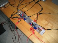
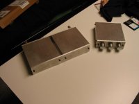
my gainclone!
Just thought I would post a picture of my gainclone. It uses Peter's simplified circuit, although I'm considering changing the 4.7uf with 22uf. Has anyone else tried this? I also have not received my transformer yet so I have it running on lab power supplies in this picture. In the next picture are the complete chassis of the control and amp. When the trafo gets here I can complete the chassis for it.
Just thought I would post a picture of my gainclone. It uses Peter's simplified circuit, although I'm considering changing the 4.7uf with 22uf. Has anyone else tried this? I also have not received my transformer yet so I have it running on lab power supplies in this picture. In the next picture are the complete chassis of the control and amp. When the trafo gets here I can complete the chassis for it.
Attachments
- Status
- Not open for further replies.
- Home
- Amplifiers
- Chip Amps
- This is not just another gainclone