Peter, where did you find that info ? Also, it would be nice to have some technical specs! I would like to compare the BG specs to the Panasonic FC specs...
Anyone ?
Fedde
Anyone ?
Fedde
Hi All,
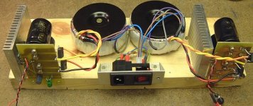
Just an update - I've converted my GainClone to dual-mono. You can see the origional version here, which used an 18V 120VA transformer to power both channels. Attached is a pic showing a pair of 25V 160VA transformers
I wasn't prepared for the improvement in sound quality! The imaging is much, much better, and the amplifier is more dynamic and powerful. I haven't detected any loss of bass with the 25V transformers. It's funny - we all know how important the PSU is, but it's nice to demonstrate it now and again 😉
There's lots more detail on my homepage, including details of the cases I plan to use.
Cheers,
Mark
Attachments
Mark - excellent idea of prototyping on a plank of wood, I've done a similar job with my PSU as the 'boxes' I have ordered are out of stock at Maplin.
And thanks for all the information on your site. I don't think that it is possible to read too much on any subject like this before building a Gainclone for yourself. Although I'm well on the way to completing my own amps, I found it very interesting to compare notes with your design.
One question - what did you use for your rectifier bridges?
well, i put my first gainclone together today... of course it wouldn´t work(allways happens to me)
its probably the ps(a regular pc-powersupply) that doesn´t deliver any electricity(god knows why, unfortunately i dont)
i guess the project will be on the shelf for a couple of days until i find a new ps.
its probably the ps(a regular pc-powersupply) that doesn´t deliver any electricity(god knows why, unfortunately i dont)
i guess the project will be on the shelf for a couple of days until i find a new ps.
Olle - I just powered up one channel of my Gainclone setup and got absolute silence! In being so careful to check everything, I had forgotten to press PLAY on the CD player 
After I did press the PLAY button, I'm glad to say that I got some sound (with an atonsihing amount of bass) through one of my old Mordaunt Short Pageant speakers. Now on to the second channel....
As regards your problem, didn't you measure the voltage from your power supply before connecting your amp to it? It sounds as though you haven't connected it up correctly. I believe there was some information on using a PC PSU earlier in this thread.
Anyway, don't give up. I usually take a break and a cup of tea whenever I hit a snag and it's surprising how often I realise what I may have done wrong. Good luck anyway.
If it is a ATX type PSU you have to start it up by shorting some pins dont remember which ones, maybe someone know.Olle Bard said:its probably the ps(a regular pc-powersupply) that doesn´t deliver any electricity(god knows why, unfortunately i dont)
Keld
Hi
IF its ATX heres a link: http://www.interlab-net.com/docs/lightworks/support/lw&hw/using_ATX_Power_supply_pinout.pdf
Keld
IF its ATX heres a link: http://www.interlab-net.com/docs/lightworks/support/lw&hw/using_ATX_Power_supply_pinout.pdf
Keld
you have to short the green to ground (black) to get it to turn on, if you are using an older powersupply you may need to put some load (like a >5W resistor) on the 5v or 12v
what parts a atx from the other types?
my connectors are npt like the ones in the atx-pdf, im going to try shorting some pins(not just randomly though, but the ones you told me)
i realise i should have measured the output from the ps.
the card with the chip(dont know what you call it but its an experiment-card with a lot of holes connected 3 and 3) is a damn mess, the chip wouldnt fit traight so i had to put it diagonally(causes a bloody mess). maybe i can borrow my friends camera and get some pics up later.
well now i got some studying to do so that will have to wait until the morning
Nuuk said:Mark - excellent idea of prototyping on a plank of wood, I've done a similar job with my PSU as the 'boxes' I have ordered are out of stock at Maplin.
And thanks for all the information on your site. I don't think that it is possible to read too much on any subject like this before building a Gainclone for yourself. Although I'm well on the way to completing my own amps, I found it very interesting to compare notes with your design.
One question - what did you use for your rectifier bridges?
Hi Nuuk,
They're just standard rectifiers - IR (International Rectifier) KBPC601 - they probably came from Farnell, they're just what I happened to have in my "stores". As you might have read on my page, I'm about to try some MUR860's
Glad you found the page useful. I've been meaning to email you and complement you on your "Decibel Dungeon" site - great site! I sometimes find it tricky to find my way around - have you got a "site map" page? Wouldn't want to miss anything!
Also, I love your GainClones - I've never thought about veneering a drainpipe 😉 I'm been meaning to ask - are the two holes on the front for the speaker connections?
Cheers,
Mark
Olle, if the connector fits on a ATX motherboard, then it should
be an ATX supply. If you are uncertain, start with a 1k resistor
between green and black (ground) instead of shorting and
check if you get correct voltages on the connector.
be an ATX supply. If you are uncertain, start with a 1k resistor
between green and black (ground) instead of shorting and
check if you get correct voltages on the connector.
I'm in the throws of building my inverted GC and have FINALLY!! read through all the posts on this thread. Whether I retained it all is another question....and I've now got some Q's of my own.
- people have recently asked about PS hookup wire besides CAT5 and I have yet to see specific responses besides Peter saying 4TC. An old friend used to use braided wire-wrap wire years ago on recommendations from Audio Amateur mag. I haven't got or really want to use CAT5. Wire-wrap wire is silver coated copper with teflon jacket and thin gauge, and I've got a bunch!...I planned on braiding 3 sets of already braided pairs for a total of 6 conductors per rail. Thoughts? Actually I was going to use this for all the hookup wire.....
- to measure the output for oscillations with my scope, do I need to run the amp into a load and if so....can I make something easily, or will I have to take an inital chance on a speaker?
- Since people go dual mono right back to the transformers, If I intend on also building a 5 channel amp using a large single Xformer, is there any reason to have seperate bridges(pair) per channel or do they interact somehow....it just seems like a fairly cheap way to go "almost" dual mono.
-This huge Xformer is 2X 29V and the surplus sign said 8 Amps I believe...is the VA rating 58V X 8A= 464VA....or 29V X 8A=232VA
If it's 464VA then I intend to build a 5 channel home theater amp. Is it big enough? I plan on dropping the voltage with a couple(few?) of diodes per rail(comments?). It has a 3 wire secondary.
John S.
Forgot to mention it's a single chassis, so the PS(and speaker) hookup wire I need advice on is internal type hookup wire.
The "chassis" is a gutted crappy/broken Pioneer DVD-434 player. What a piece of junk...so I gutted it and modified the case to accept heatsinks and the like. With a gloss piano black 1/2" MDF front panel....definitly low budget, but it would fool most. I'll post pictures when I'm done. After seeing it though you will realise that there may actually be a use for all those old crappy 70's receivers.....or crappy 2001 DVD players!! Chassis dampening may be required😉
John S.
Soucie said:
- Since people go dual mono right back to the transformers, If I intend on also building a 5 channel amp using a large single Xformer, is there any reason to have seperate bridges(pair) per channel or do they interact somehow....it just seems like a fairly cheap way to go "almost" dual mono.
-This huge Xformer is 2X 29V and the surplus sign said 8 Amps I believe...is the VA rating 58V X 8A= 464VA....or 29V X 8A=232VA
If it's 464VA then I intend to build a 5 channel home theater amp. Is it big enough? I plan on dropping the voltage with a couple(few?) of diodes per rail(comments?). It has a 3 wire secondary.
John S.
A 3-wire secondary won't allow you to use seperate bridges for the +ve and -ve rails. Also, earth management will be tricky, especially for 5 channels. It will work, but expect low levels of 100Hz hum on the output when you connect the signal grounds of the amps together via a preamp...
Also, 29V might be a little high, depending on which IC you plan to use. Check the GainClone page on my website for quite a bit of background on this - my 25V secondaries resulted in nearly 40V after rectification, which is pushing things a bit for an LM3875. Droping the voltage with diodes will work, but it strikes me as a bit crude. These things are so cheap to build, why compromise with something as fundamental as the PSU?
Based on my recent experience, I strongly recomend you consider using seperate transformers 😉
Good luck with your project!
Mark
Thanks for pointing out the 3 wire/single bridge point. I probably confused you a bit. I actually am building a 2 channel gainclone that I already have a 25V-25V 300VA - 4 wire secondary Xformer sitting around for. I am ALSO building a 5 channel amp that I am trying to keep on the cheap side...hence using a Xformer I laready have from surplus.
So I guess the question still stands....if I use a 3 wire secondary and a single bridge....is there any value in parallelling 5 bridges Or alternatly....should I use 4 MUR860 only vs 5 seperate common bridges(cheap). Remember this is Home Theater here, my "good" stereo version is a whole other ball game.
ohn S
Well folks, I speak to you from the relative safety of my computer chair having escaped from a small room upstairs where I was 'trapped' with some items known here as Gainclones! 😉
I went up after the Grand Prix to connect and test the second channel of my monobloc amps and made the big mistake of then running some music through them. And I just couldn't stop listening. Do they really get better after more burning in?
I haven't enjoyed a listening session so much for a long long time and only stopped bacause the room is adjacent to my neighbours bedroom and I just couldn't stand any longer.
As of now, I can't imagine wanting to tweak anything but I'm sure the bug will return eventually.
For those interested, the component details are: 120va transformer with single rectifier bridge (MUR860's) and no caps in the PSU. Panasonic 1000ufd/50v decoupling caps with LCR polyprop 0.1ufd to bypass. 57K metal film resistor from input to ground. 47ufd Black Gate NXQ (I had a couple laying around) and carbon film 10K input resistor (inherited from my late father so source unknown), feedback resistor (two actually) 432K Welwyn RC55's.
And the test set up is far from optimum, a bog standard Cambridge D300 CD player sitting on a couple of pieces of blockboard on a chest of drawers. A couple of amps sitting on the Cd player providing a platform for the Gainclones and PSU. A cheap 100K 'pot in a box' between CD player and amps. And still only one of the 120va PSU's built!
Speakers used were a pair of old Mordaunt Short Pageants (very efficient) fed through good old QED 79 strand speaker cable.
I know everbody said the Gainclones were good but I wasn't expecting what I just heard. And where do the little s*ds get all that bass from?
Listening to a compilation CD I was trying to sum up the sound of the Gainclones when an Eva Cassidy track came on and I think that the Gainclones display the same sort of qualities. Delicate when they need to be but powerful when called for. Great clarity, silky smooth, timing spot on and very musical. And that after only my first session. I'm almost too excited to go to bed
Mark - I believe that Peter Daniel is now using the MSR860 diodes but you won't be disappointed with the MUR860's. And yes, the holes at the front are for the speaker connections but they kind of give the housing a personality too 🙂
Decibel Dungeon has grown so big that I had better stop building things and review the navigation tools. Thanks for pointing it out.
Soucie said:I'm in the throws of building my inverted GC and have FINALLY!! read through all the posts on this thread. Whether I retained it all is another question....and I've now got some Q's of my own.
- to measure the output for oscillations with my scope, do I need to run the amp into a load and if so....can I make something easily, or will I have to take an inital chance on a speaker?
- Since people go dual mono right back to the transformers, If I intend on also building a 5 channel amp using a large single Xformer, is there any reason to have seperate bridges(pair) per channel or do they interact somehow....it just seems like a fairly cheap way to go "almost" dual mono.
John S.
What a long thread eh ?
Nice that these gainclone thingies are so popular these days ;-)
You could try to measure potential oscillations of the gainclone with a resistive load. But it is more likely that oscillations will occur with a capacitive load. You could try to add a capacitor in parallel. Also, measure the dc voltage of course before connecting of course...
Having seperate bridges could be an advantage yes. Beside improved channel seperation, the diodes are less stressed by the amount of current. Also regard the diode specs when you put diodes in series. The amount of current could reach 5-10A.
Fedde
- Status
- Not open for further replies.
- Home
- Amplifiers
- Chip Amps
- This is not just another gainclone