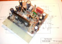
In the third schematic, shouldn't Q13 be MJL1302A?
I always thought PCBs without silkscreen looked gaudy, but you make it look good. Most PCBs are that awful yellow-brown...
Second schematic, and yes you are correct.
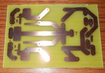
Thanks, and there is a silkscreen.
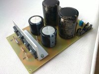
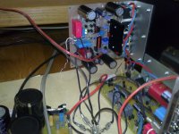
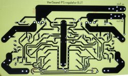
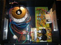
All PCBs are ready. Now is time to start some measurements, but first I will listen some music over this PCBs connected together. ThermalTrak bias current is very stable from 25 degree to 60 degree centigrade. I will show a result after I finish test measurements. For now here are all needed PCBs.
dado
dado
Attachments
Gad,
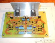
the thickness of the L angle for connecting to the heatsink is too thin.
4 devices can dissipate a lot of heat.
Try for at least 50% thicker and if you can source it, double the thickness.
The two device version is possibly OK.
the thickness of the L angle for connecting to the heatsink is too thin.
4 devices can dissipate a lot of heat.
Try for at least 50% thicker and if you can source it, double the thickness.
The two device version is possibly OK.
Gad,
the thickness of the L angle for connecting to the heatsink is too thin.
4 devices can dissipate a lot of heat.
Try for at least 50% thicker and if you can source it, double the thickness.
The two device version is possibly OK.
Thanks Andrew, the thickness is 3 mm and I never have any problem with heat transfer to the heatsink. By the way I could not find thicker alumina here in Zagreb.
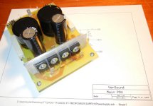
Two device version is the Power Suply Regulator, a kind of a capacitor multiplier.
dado
Listening
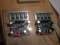
Both channels are playing now. It is to early to final comment of the sound, but I like it, very punchy bass well controlled clean mid and heights.
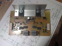
I wanted very well thermal control of the output stage bias. I divided this in two part. First the drivers are situated on separate heatsink together with the bias transistor (BD139). The bias spreader use ThermalTrak diodes connected in the bias transistor emitter. In this way I tried to separate thermal drift of the drivers from the output ThermalTrak transistors. The bias spreader transistor it self has to compensate thermal drift of the drivers and ThermaTrak diodes have to compensate thermal drift of the ThermalTrak output transistor only.
And I think the result is quite good. In first seconds after power on the bias current will go up from 60 mA (per output pair) to 130 mA and after the driver temperature have settled, temperature increment of the output transistor will no influences the bias current. It stays at between 125 mA to 130 mA. I was measuring the voltage drop on the output transistors emitter resistor and it stay quite firmly at 20 mV.
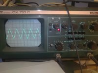
Next, I m going to do some measurements with sinus, triangle and square waves. I will insert different value capacitors parallel to the dummy load.
Dado
Both channels are playing now. It is to early to final comment of the sound, but I like it, very punchy bass well controlled clean mid and heights.
I wanted very well thermal control of the output stage bias. I divided this in two part. First the drivers are situated on separate heatsink together with the bias transistor (BD139). The bias spreader use ThermalTrak diodes connected in the bias transistor emitter. In this way I tried to separate thermal drift of the drivers from the output ThermalTrak transistors. The bias spreader transistor it self has to compensate thermal drift of the drivers and ThermaTrak diodes have to compensate thermal drift of the ThermalTrak output transistor only.
And I think the result is quite good. In first seconds after power on the bias current will go up from 60 mA (per output pair) to 130 mA and after the driver temperature have settled, temperature increment of the output transistor will no influences the bias current. It stays at between 125 mA to 130 mA. I was measuring the voltage drop on the output transistors emitter resistor and it stay quite firmly at 20 mV.
Next, I m going to do some measurements with sinus, triangle and square waves. I will insert different value capacitors parallel to the dummy load.
Dado
Attachments
bravo
Congratulations!
the sound is better than from your JHLs?
Both channels are playing now. ....
Next, I m going to do some measurements with sinus, triangle and square waves. I will insert different value capacitors parallel to the dummy load.
Dado
Congratulations!
the sound is better than from your JHLs?
Congratulations!
the sound is better than from your JHLs?
Not sure yet, this amp has to play some time as electrolytic caps need a time to reform(thay stayed in my drawer) One think is certain, bass is more puchy and better controled.
JLH amp realy a treasure (after my modest improvement) and I like it. It uses original Hitachi lateral, I am not sure how it will work with other producers lateral.
dado

Thanks Lazy Cat!Nice one
What's output L inductance? Output impedance at 20 kHz?
Andrej
I am not sure, did not do any measurement yet. As it uses triple OPS and very high NFB(70dB at 20kHz) it should be quite low.
dado
TT-triple
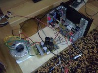
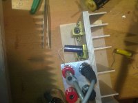
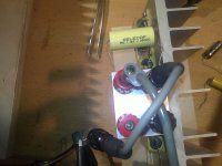
I've been building the amp in parallel with Dadod, on my side of the Atlantic. He has been very helpful answering my questions and guiding me through my first fully discrete DIY amp. He was kind enough to send me the amplifier PCBs and heatsinks (not available in the USA).
Many thanks, Dadod!
So far I've constructed the power supply, DC regualtor/speaker protection, and almost have one channel complete. After I have the first channel operational, I will begin the second.
I made a parts list, which I've shared on Google Docs.
A few more steps I should be ready for the light bulb test.
Here are a few photos:
Attachments
-
 tt_triple_4.jpg177.2 KB · Views: 405
 -
 reg_bjt_3.JPG235.5 KB · Views: 804
 -
 psu.JPG206.7 KB · Views: 807
 -
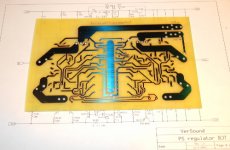
 reg_pcb_backlight.JPG205.4 KB · Views: 825
 -
 PSU_Regulator_PCB.JPG148.9 KB · Views: 838
 -
 power_supply_pcb.JPG148.4 KB · Views: 869
 -
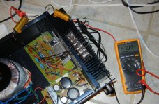 reg_bjt_test_4.jpg362.8 KB · Views: 351
 -
 chassis_2.jpg608.4 KB · Views: 330
 -
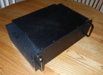 chassis.jpg252.9 KB · Views: 355
Last edited:
Last edited by a moderator:
 Hi greenm01 I added a tag that your link was youtube as there are some members on limited bandwidth or who get logged at work if they go to youtube. No biggy but probably a good idea to tag when you post 🙂
 Tony.
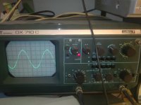
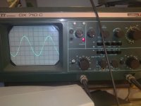
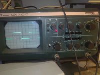
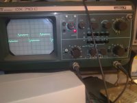
Next is 1uF parallel to the 8 ohm load at 20kHz. Durin the test I overloaded the amp and the power supply protection switched off the power. Reset was done by switch off and after some seconds switch on again, and all worked.
dado
dado
Attachments
Well done!
I agree with your approach to thermal compensation, I did a lot of (theoretical) study of that approach a while back and it seemed ideal. Looks like it is working very well for you.
I agree with your approach to thermal compensation, I did a lot of (theoretical) study of that approach a while back and it seemed ideal. Looks like it is working very well for you.
meaurements
Hi, Dado.
The amp is sounding worderful: punchy bass, smooth mids, and aggressive highs. I'm looking forward to completing the second channel.
A few questions in regard to the TT-Triple:
With headphones I don't notice white noise with line level portable media players and computer audio output.
/Mason
Hi, Dado.
The amp is sounding worderful: punchy bass, smooth mids, and aggressive highs. I'm looking forward to completing the second channel.
A few questions in regard to the TT-Triple:
- Do you happen to know the input sensitivity?
- Have you been able to measure real-world THD?
With headphones I don't notice white noise with line level portable media players and computer audio output.
/Mason
With the Power Amplifier input shorted you should not be able to hear any noise from the connected speaker.
If you can then the amp has too high a noise level for that speaker.
If my amps measure <=0.1mVac, I generally cannot hear any noise from the speakers I use.
If you can then the amp has too high a noise level for that speaker.
If my amps measure <=0.1mVac, I generally cannot hear any noise from the speakers I use.
- Status
- Not open for further replies.
- Home
- Amplifiers
- Solid State
- ThermalTrak+TMC amp