Sounds correct and 0.1sec discharge time is equivalent to 10Hz lower bandwidth. This is a good value.
Hello All,
I am just about ready to test the Yarra PS without the DB. I have a few nagging noob questions That I need help with. No laughing allowed😉 , trying to learn.
1. What are builders using for the 2 fuses in the Schurter power inlet. I have some 125V/4A fuse's. Are they OK?. On the circuit label on the module there is "2 x 1.6W fuses" 🤔
2. The trim resistors: If they are quoted as being 25 turns, is there a hard stop when turning the screw. The one I tested holding in my hand, the screw seemed to turn forever. Hard to find the mid-point of the trimmer. 🤔
3. For the 1st power up and testing / setting voltage on the PS, xrk971 quoted: " I connected alligator clips to the output and monitored on DVM ". My question is "Is X161 the output being quoted" ? If so, do I attach the ribbon cable to X161 and then use aiiigator clips to set each trimmer separately. For example set the trimmer voltage measuring between X161-8 and X161-7 ( gnd). Otherwise please correct me with an explanation, or doctor up my picture attached to show me how. Also included schematic. Thanks as always for the help.
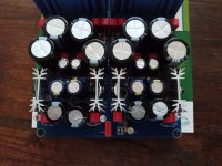
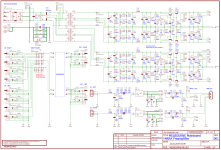


1) 4 amp fuses are too large. You want the fuses to blow before taking out components if there is a fault. I think I used 250V 0.5 amp slow blow fuses in my Yarra.
2) There is no hard stop when turning the trim pots, but when you get to the end you can hear a soft click as you keep turning. At that point you can start counting your turns back in the other direction.
3) Hopefully X will chime in on this. I can't remember the exact pinout, but you will want to probe V+ and ground, then V- and ground. I remember placing thin leads cut off from resistors and placing them in the correct holes and probing them, and making sure they didn't touch together and short. There must be a better way though.
Thanks for the info Alan. Let's see if X or Vunce will give me some hints. For #2, I will have to put my hearing aids in 😉
For #3, Rather than inserting leads, I thought I would attach the ribbon cable to X161, and then attach the pin out pad to the empty end of the ribbon cable. I would then use some small alligator clips to test, if enough room to attach the clips.
Cheers
For #3, Rather than inserting leads, I thought I would attach the ribbon cable to X161, and then attach the pin out pad to the empty end of the ribbon cable. I would then use some small alligator clips to test, if enough room to attach the clips.
Cheers
Hi Myles,
You can probe the exposed resistor leads that goes to the LED to check for voltages. Make sure it’s upstream of the resistor (not between resistor and LED). Connect the DVM +ve (red) test probe to the 4 resistors. Keeping the -ve (black) probe on ground. We should have provided a suitable easily accessible ground but I had to scrape away some solder mask and solder a small wire lead with a loop on the ground plane in order to access ground (0v) on the board.
This lets you check the voltages. Here is marked up schematic showing where to check:

Be careful not to let the alligator clips touch each other and short out when testing if using ribbon cable as breakout. The Arduino DuPont style hookup wires with a metal tip are good for probing as they can be inserted into the holes in the sockets and provide enough stand-off to not cause shorts. Like these:

You can probe the exposed resistor leads that goes to the LED to check for voltages. Make sure it’s upstream of the resistor (not between resistor and LED). Connect the DVM +ve (red) test probe to the 4 resistors. Keeping the -ve (black) probe on ground. We should have provided a suitable easily accessible ground but I had to scrape away some solder mask and solder a small wire lead with a loop on the ground plane in order to access ground (0v) on the board.
This lets you check the voltages. Here is marked up schematic showing where to check:
Be careful not to let the alligator clips touch each other and short out when testing if using ribbon cable as breakout. The Arduino DuPont style hookup wires with a metal tip are good for probing as they can be inserted into the holes in the sockets and provide enough stand-off to not cause shorts. Like these:
Thank you for the info X. Thinking about the ground, Could I solder a single header into X-181-2 as it is labeled as ground. X181-1 would be unpopulated. Or, can I use the SK104 heatsinks as a ground.
Those Arduino pins are too fat to fit in the ribbon cable header and will damage the sockets if forced in.
Use the locations X pointed out to verify V+ and V-
Use X181-2 as your GND reference.
Edit: Probably better to use the HS pads as GND since this psu is dual mono and X181-2 is part is the right side section, no continuity to the left section.
Use the locations X pointed out to verify V+ and V-
Use X181-2 as your GND reference.
Edit: Probably better to use the HS pads as GND since this psu is dual mono and X181-2 is part is the right side section, no continuity to the left section.
Last edited:
Thanks Vunce for the info. HS are soldered to the pads already. OK to use the actual sink as ground ? I may have to get creative if I need to attach a probe to the soldered HS pad.
I will have to think about this for a bit. Maybe Alan's idea with resistor leads in the X161 (if they fit without damage) can work.
I will have to think about this for a bit. Maybe Alan's idea with resistor leads in the X161 (if they fit without damage) can work.
With the attached image, am I correct in the following number sequence for X161. I tried to follow the schematic and lines on the pcb. Hard to tell where they attach to lines or planes
So from bottom left side of image going upwards: 8, 5, 4, 1 and from right side of image going upwards: 7, 6, 3, 2
Left side corresponds to downstream resistors and right side is the grounds with resistors and leds.
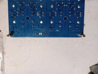
So from bottom left side of image going upwards: 8, 5, 4, 1 and from right side of image going upwards: 7, 6, 3, 2
Left side corresponds to downstream resistors and right side is the grounds with resistors and leds.

A little help please. I have soldered the HS's to the pcb. Can the HS's be used as ground reference when testing ?
If I cannot use the HS's as ground, then, when looking at the image shown in above post , could you tell me if the grounds are on the right side or the left side of X161 and what is the X-161-? nomenclature associated with each ground. I hope the grounds and voltage points do not alternate from side to side.
Once I have this confirmed, I think I will desolder X161, and use some headers to test the psu voltages, rather than trying to stick some leads into the X161 header.
Thanks for clarification and help
Soldering flying leads on the bottom side on the corresponding resistors pads before desoldering X161?
JP
JP
Thanks JP, that will help with attaching a probe to the resistor. Somehow the main point of post#1610 was lost.
I need to know:
1. Can I use the heatsinks as ground, then I would not have to desolder X161.
2. If I can not use the heatsinks as grounds, can you tell me if the ground points on X161 are on the right side or the left side according to the image posted in post #1609.
3. What is the X-161-? nomenclature associated with each ground. I am sorry, I can read the schematic, but I can not decipher all the lines around X161 from looking at the bottom of the pcb.
MM
Thanks JP,
So if I am reading this correctly I could:
1. Use the heatsinks as grounds. The heatsinks are soldered to pcb or I could,
2. Use x181-2 as right ground, and insert a suitable lead into the ground point on X161 shown for left ground.
Both of these would eliminate desoldering of X161.
Am I correct in this reasoning?
MM
Use for the grounds the grounds on the soldered heatsinks, yes, no wire or lead into connectors.
JP
JP
Thanks for the help JP. I will solder some wire extensions onto the resistors for easy access.
MM
MM
JP, X, others,
I have been searching extensively for the 400V 10A rectifying diodes for V1041, V1042, V1043,V1044 on the Yarra board.
Are there any maximum or minimum parameters for these: for example: could I use a 1000V 10A diode or on the minimum end a 400V 3A or 400V 6A rectifying diode. Need some guidelines.
Thanks for the help.
I have completed the Melbourne DB and mounted on the Yarra MB. See pics of mounting below. I did not use any insulating tape or insulating washers, as all the screws were well inside the white marker dimensions and not near any via's. I hope this is OK? Otherwise I can change if necessary.
Also, On the Yarra PS, is there supposed to be a standoff inserted underneath each of the Talema transformers, so the top of the screw/bolt is resting in the small hole of the transformer. I did not do this, so I am asking if this is necessary?
Thanks for the help,
Regards
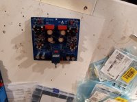
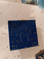
Also, On the Yarra PS, is there supposed to be a standoff inserted underneath each of the Talema transformers, so the top of the screw/bolt is resting in the small hole of the transformer. I did not do this, so I am asking if this is necessary?
Thanks for the help,
Regards


- Home
- Group Buys
- The YARRA Preamplifier/HPA for Melbourne DB Group Buy