Hello xrk971, i have interest.Hi Folks,
If there is any interest in the new Yarra PSU with micro active bridges and low noise LDO regulators shown here:
The YARRA Preamplifier/HPA for Melbourne DB Group Buy
Please let me know. It really is the ultimate state of the art in low noise linear regulated PSUs for preamps and headphone amps.
I can revise the prototype for production if we can get some interest going. If you don’t mind working on the prototype by adding a few solder jumpers. Let me know.
Hi X,
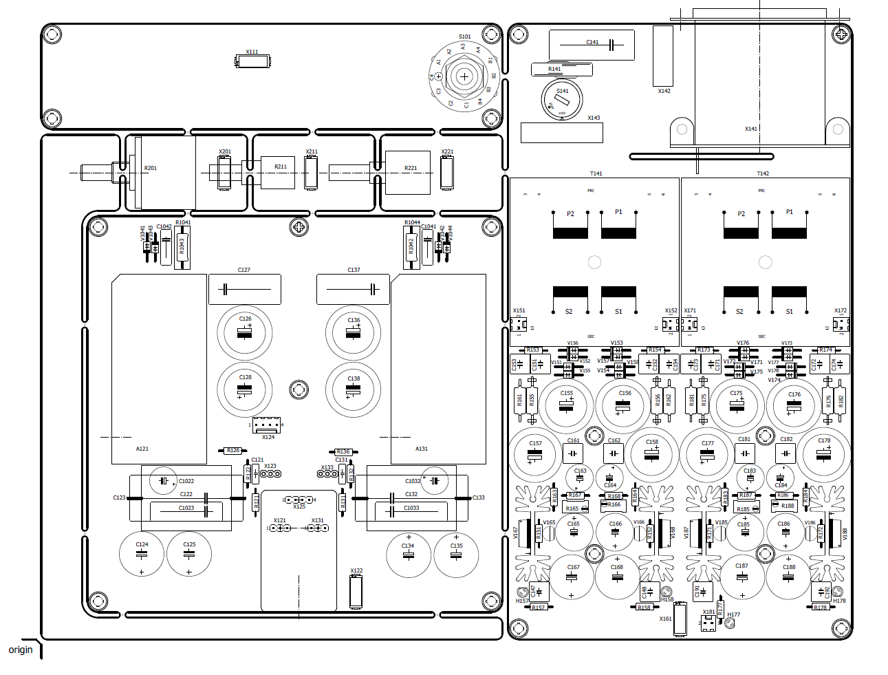
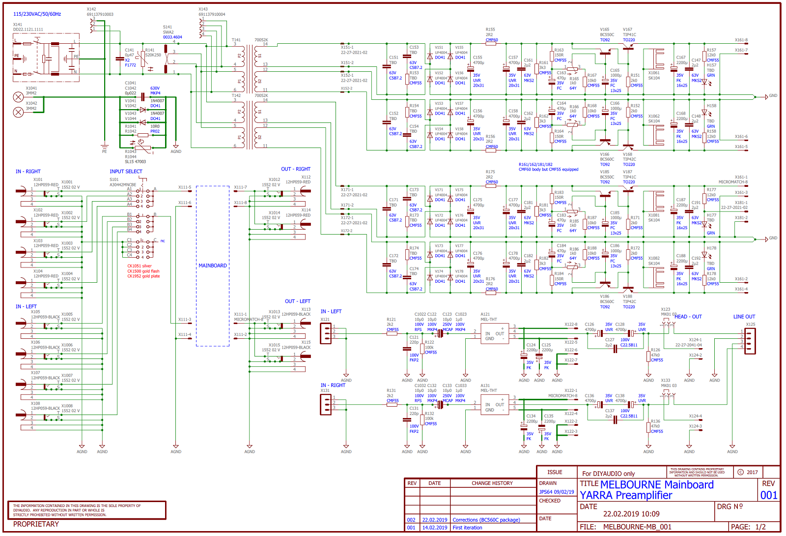
In the Yarra pre project, there is a 4-pin female connector on the little volume control PCB, labeled X125. It connects a to a 4-pin male connector on the motherboard (MB). I can't find the mating 4-pin connector on the schematic, and I believe there may not be one, other than possibly a ground. It may be there for support only? Is that a correct assumption, or are there other electrical properties used by the X125 connector?
Edit... Is that the output of the volume board? It does appear to go to connectors x123 and x133.
Edit 2... I believe x121, and x131 are the outputs from the volume control?
Last edited:
Hi Redjr,
Look at the second page of the PDF of the schematic on post 1.
https://www.diyaudio.com/forums/att...ifier-hpa-melbourne-db-buy-yarra_sch_001a-pdf
Each volume pot board has a different designation (x204, x214, x224). But they all connect to the same 4pin male header for the volume pot x125 on the MB.
Got it. My original printout of the schematic had cut off the right side that included the x125 connector. Clear as mud now. And, I never did print page 2. My bad!
No worries, redjr. I am glad there is renewed interest in the Yarra. I am getting some questions from Stuntfingers who is about to start his build. He was asking where the stuffing diagram was.
It’s also on Post 1 as PNG graphic and as pdf.
PDF here:
https://www.diyaudio.com/forums/att...r-hpa-melbourne-db-buy-yarra_pba-top_001a-pdf
It’s also on Post 1 as PNG graphic and as pdf.
PDF here:
https://www.diyaudio.com/forums/att...r-hpa-melbourne-db-buy-yarra_pba-top_001a-pdf
Thanks for that. It's a little better quality than what I had. I'll have a sneak-preview/reveal of a fun upgrade I've done to the Yarra pre in a couple weeks. Hopefully, it will spark some renewed interest in ver 2. 🙂
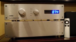
Yarra Muserized
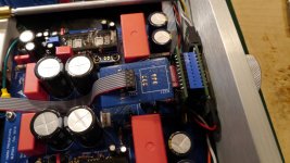
I built the Yarra pre about a year ago. It is a beautiful sounding pre with customizable modules. However, I missed having a remote volume control. So, I decided to add a Muse volume control module inside the existing case. The Muse control I used was a project by member meldano he created a couple years ago. Information on this project can be found here.
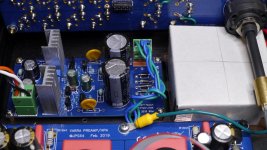
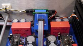
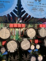
As most of you know, there is not much 'extra' space inside the Yarra. Getting everything to fit was a little challenging, but obviously doable. The module requires +-15V, and includes an onboard regulator supplying 5V for the micro-contoller and display. I decided to use a separate supply, with a small toroidal tranny under a DIY'ed faraday cage to help minimize noise. The meldano project is available in SE output, or using 2 stereo boards - balanced as well. The display is optional as well. To attach the VC I used one of the small unused PCB included with Yarra kit. That was the simplest plug-n-play replacement and worked effectively.
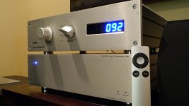
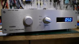
Below are some pictures of my install inside the Yarra, as well as the finished revised chassis. As you can see, it was a pretty tight fit of everything. I polished off the mod with the front panel being 'redone' by FPE to support the display, and my input/selection text.
With very limited testing in my system using X's new class D amp, I've been impressed. I can't hear any noise introduced by the controller, and the volume has 240 steps! One nice addition is, the project uses the ubiquitous Apple remote for volume up/down and mute. Very convenient.
I built the Yarra pre about a year ago. It is a beautiful sounding pre with customizable modules. However, I missed having a remote volume control. So, I decided to add a Muse volume control module inside the existing case. The Muse control I used was a project by member meldano he created a couple years ago. Information on this project can be found here.
As most of you know, there is not much 'extra' space inside the Yarra. Getting everything to fit was a little challenging, but obviously doable. The module requires +-15V, and includes an onboard regulator supplying 5V for the micro-contoller and display. I decided to use a separate supply, with a small toroidal tranny under a DIY'ed faraday cage to help minimize noise. The meldano project is available in SE output, or using 2 stereo boards - balanced as well. The display is optional as well. To attach the VC I used one of the small unused PCB included with Yarra kit. That was the simplest plug-n-play replacement and worked effectively.
Below are some pictures of my install inside the Yarra, as well as the finished revised chassis. As you can see, it was a pretty tight fit of everything. I polished off the mod with the front panel being 'redone' by FPE to support the display, and my input/selection text.
With very limited testing in my system using X's new class D amp, I've been impressed. I can't hear any noise introduced by the controller, and the volume has 240 steps! One nice addition is, the project uses the ubiquitous Apple remote for volume up/down and mute. Very convenient.
Attachments

Fantastic work Redjr!
It is a tight fit, but you squeezed it in just fine.
I’ve been interested in the same volume control, very good to know the Yarra stays quiet with the additional circuitry.

It is a tight fit, but you squeezed it in just fine.
I’ve been interested in the same volume control, very good to know the Yarra stays quiet with the additional circuitry.
Thanks for the kind words. It was a fun project, and turned out the way I had intended. I hope there's not too much noise banging around in there, that may be affecting the pure audio signal. Now I can adjust the VC from my easy chair! 🙂 The nice feature of the Muse is that you simply wire it in-place of any normal analog volume control. That makes it easily adaptable to just about any pre, or amp. As I mentioned, the little VC PCB's that came with the Yarra made it super simple to adopt.
Let’s see if we can make one with an integrated 3A at 5v supply. Probably a CMC in between it and the RPi.
Hi X, Just curious.... Any further progress on mods/redesign to this PSU to support RPi current requirements? If Jan needs someone to test a prototype I'm willing. 🙂
I’m keen to hear if this progressing too. RPI with DAC and pre, including remote volume control, remote line out selection and display would be very nice.
On a side note has anyone had the Yarra tested with an AP analyser or similar?
On a side note has anyone had the Yarra tested with an AP analyser or similar?
Hi guys,
Can you clarify your requirements for the RPi psu?
Current, voltage, input (mains AC or 12v or 24v DC etc) ? We will have to make a stand-alone low noise regulated high current supply. New project.
Can you clarify your requirements for the RPi psu?
Current, voltage, input (mains AC or 12v or 24v DC etc) ? We will have to make a stand-alone low noise regulated high current supply. New project.
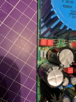
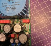
I’ve just finished the power supply for the Yarra but when I powered it on its smoked a little from the resistors R155, R156, R175 and R176, I used 2.2 ohm 1w Panasonic resistors.
I switched it off immediately so hopefully I haven’t damaged anything else. The unit was built using the BOM created by Vunce and I triple checked the component values against the schematic but the WIMA caps were TBD but I thought I’d picked the correct ones for the 22v Talema, I’ve used 2.2uF 63v WIMA film caps. Have I made a mistake with the cap selection for C151 - C154 / C171 - C174?
I switched it off immediately so hopefully I haven’t damaged anything else. The unit was built using the BOM created by Vunce and I triple checked the component values against the schematic but the WIMA caps were TBD but I thought I’d picked the correct ones for the 22v Talema, I’ve used 2.2uF 63v WIMA film caps. Have I made a mistake with the cap selection for C151 - C154 / C171 - C174?
Attachments

Hi Stuntfingers,
Sorry you are having trouble. When a series resistor of a CRC smokes, something downstream is shorted. What is the resistance of the downstream lead with respect to ground? It should not be in single digit ohms.
Couple of things to look for:
1. Solder bridges between the traces with exposed vias.
2. Incorrect BJTs installed (NPN vs PNP) in the cap Mx.
3. Reverse polarity on the electrolytic caps.
If you can remove the connections leading to the large TO-220 BJT's, then you can debug safely. The DC voltage at that resistor should be as expected 1.41x 22v = 31vdc under no load.
Thanks for the reply. Having gone over the board I have found the following:
1. No solder bridges
2. Correct BJTs installed
3. Caps have correct polarity.
I have checked the downstream leg of the resistor (R155 for example) and get zero resistance to GND when using the heatsink as GND reference, same happens when checking the LED.
I see most of the builds show the transistors thermally coupled but electrically de-coupled from the heatsink. I used thermal paste and have electrically coupled the transistor tab to the heatsink, is this my problem?
I having real issues desoldering the heatsink form the PCB. regrettably I soldered the heatsink legs it before testing.
That’s your problem: the collector is the tab so you have your wires from the CRC connected straight to ground. Always use insulator silicone spacer sheets and nylon shoulder washers with metal tab transistor packages.
If you have a hot air pencil/gun try pre-heating it from the bottom with the hot air and then using a thick chisel tip iron with a lot of solder. Alternatively, leave the heatsinks and heat only the pins of the BJTs and pull them out.
If you have a hot air pencil/gun try pre-heating it from the bottom with the hot air and then using a thick chisel tip iron with a lot of solder. Alternatively, leave the heatsinks and heat only the pins of the BJTs and pull them out.
- Home
- Group Buys
- The YARRA Preamplifier/HPA for Melbourne DB Group Buy