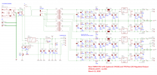
I have 8 boards that I can make available right away - they are nicely done with ENIG finish. I am getting green lately as the board house is starting to charge a hefty premium for blue boards lately as no one else is making stuff in blue I guess? It's a CRC PSU with a bridge and 78xx/79xx regulators, so not really much to go wrong. The main things are the 78xx/79xx pin arrangement (and visually that looks good), and the other thing are the pins for the LT4320 (visually that also looks good).
So let's say 2 weeks.
Vunce actually might be able to build the verification board before I do, so maybe a week or two?
Here is the schematic. I forgot to mention that there is also an LC filter stage after the CRC. So really a CRCLC filter after the LT4320 bridge, and before the TPS7Axx LDO's. There is an R in parallel with the L to dampen out any possible oscillations.
Attachments
Last edited:
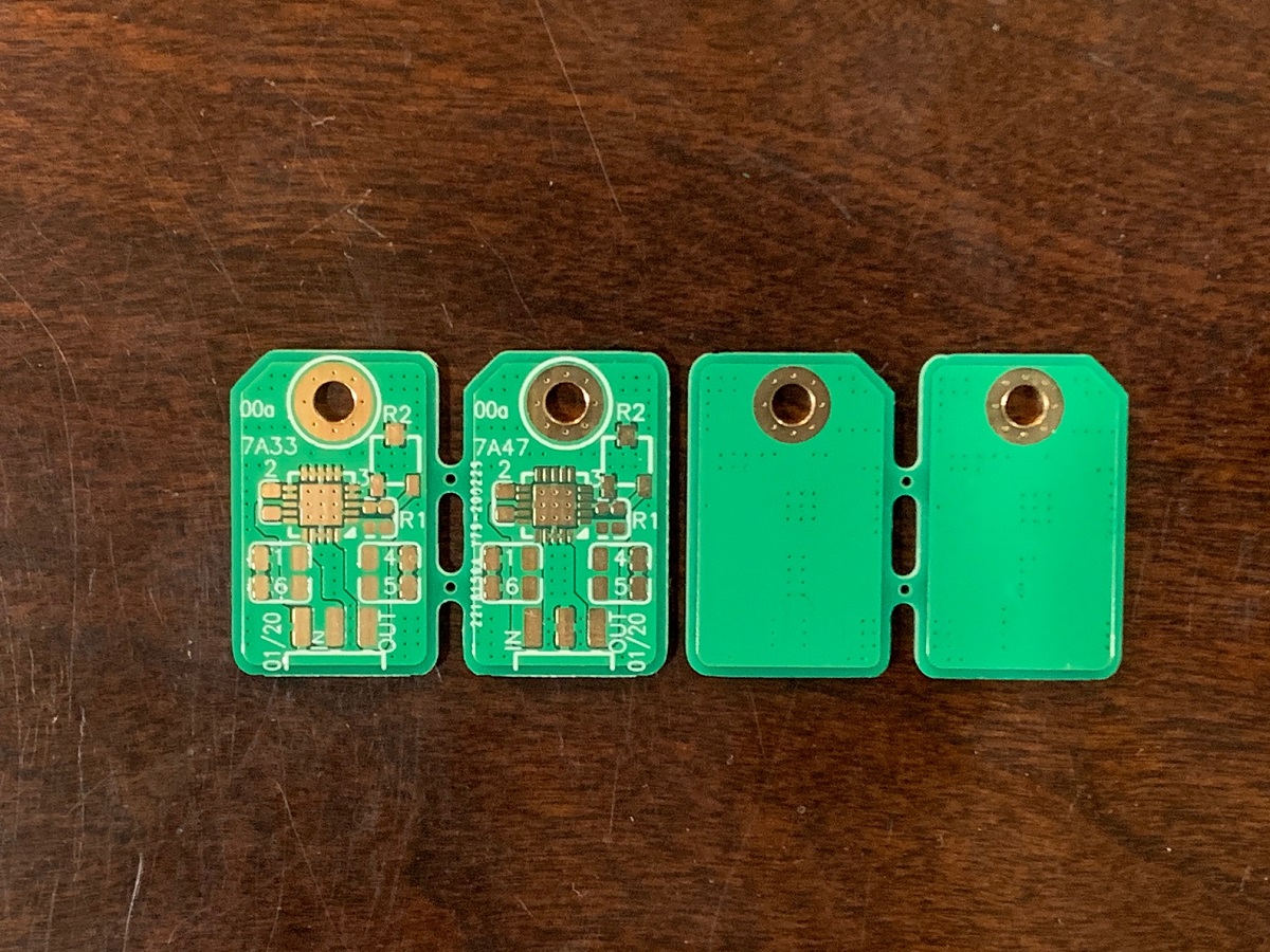
hey the PSU looks great - I especially like the TO220 LDO boards 😀 If nothing else would be interested in picking some of those up!
Are those planned to be listed separately or will it be planned as a set with main PSU board?
Are those planned to be listed separately or will it be planned as a set with main PSU board?
The TO-220 LDO boards will be sold separately. I need to test them out first.
Again, very simple I am basically 100% sure it’s going to work! I don’t have those SMT pots on hand though.
Again, very simple I am basically 100% sure it’s going to work! I don’t have those SMT pots on hand though.
No, just offering another option for those who need voltage regulation. For some IC opamps there is a hard limit on a safe voltage of say, +/-18v or +/-15v etc. For most of the discrete parts preamp designs that we have already, the voltage is flexible. For example the Melbourne can work from 24v to 32v (or more depending on resistor settings). Noise performance of the LDO’s is better if you are looking for the ultimate 40uV rms, but audibly, can you hear the difference between them? Maybe not.
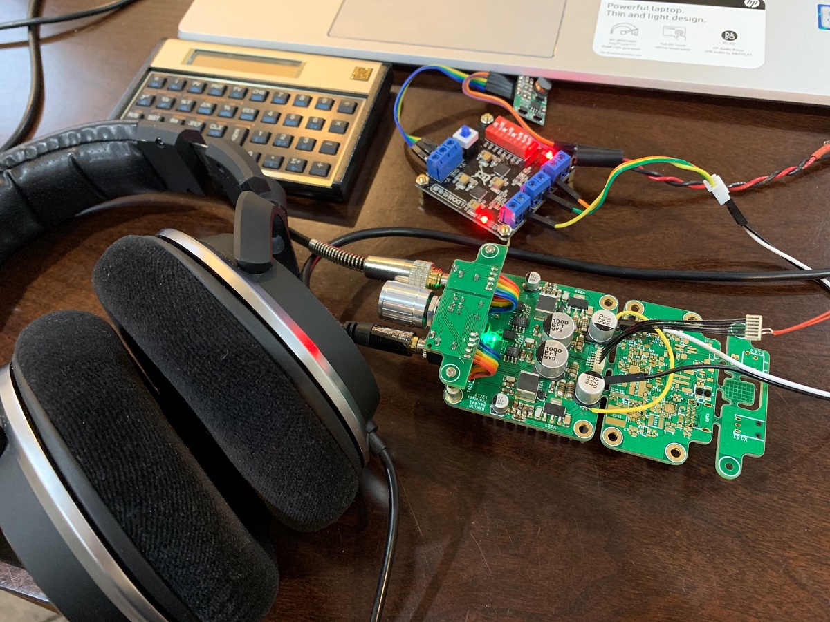
After hearing how good the Hakuin sounds as a headphone amplifier over in this thread, I knew that this just has to be offered as a preamp/HPA module for the Yarra. The sound is incredible - extremely resolving but non-fatiguing. It has immense bass clarity and great dynamics. Recording details are brought out clearly and the soundstage is accurate, wide and impressive. The topology was developed by Hugh several years ago as a possible variant for my Pocket Class A (but never released), and which has since then, transformed into the new high tech Hakuin headphone amplifier with LiPo battery management, DC-DC step up, low noise LDO, and battery level meter witha 3D printed case.
Here is the Hakuin HPA under listening tests (PSU sub section still to be built):
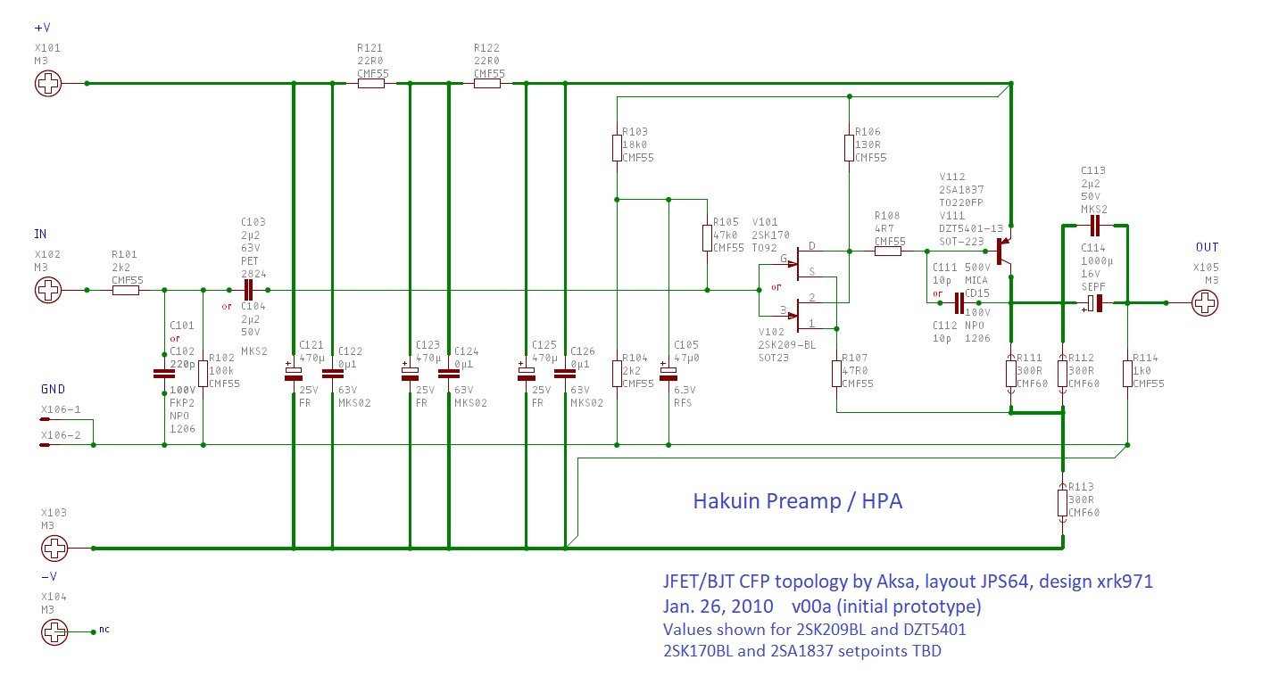
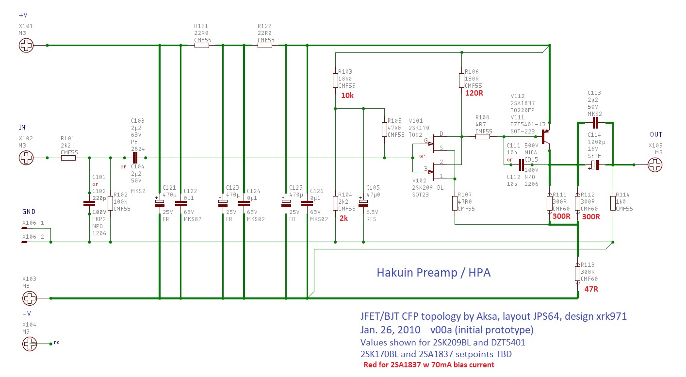
The circuit is about as simple as it gets - an N channel JFET as the master driving a PNP BJT as the slave running at a good bias current in SE Class A operation. The original one I made used a BF862 and 2SA1837. For all SMT assembly on the Hakuin HPA, I chose the still available 2SK209BL for the JFET and the DZT5401 BJT which can handle some power. For the Yarra module however, we are also adding the option of using the Toshiba Duo of 2SK170BL and the 2SA1837 - both now unobtanium, but perhaps the pairing of the finest JFET and BJT ever made or ever will be made for audio in a glorious union. I still need to calculate the resistor setpoints for the 2SK170BL and 2SA1837, but the 2SK209BL and DZT5401 as shown in this schematic are good to go. Gain is about 12dB and btw, this could be used as a great input module on the M2X power amp. Design is for 24v single rail, so perfectly compatible with upper rail of a 25w Class A amp.
A big thanks to Hugh for the circuit and inspiration, and big thanks to JPS64 for the wonderful layout!
The CFP (Sziklai pair) topology is very fast, and I believe this is where the extra resolution comes from. I am looking to building this with the 2SK170BKL and 2SA1837.
Schematic:
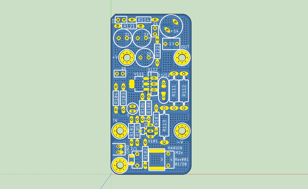
PCB top:
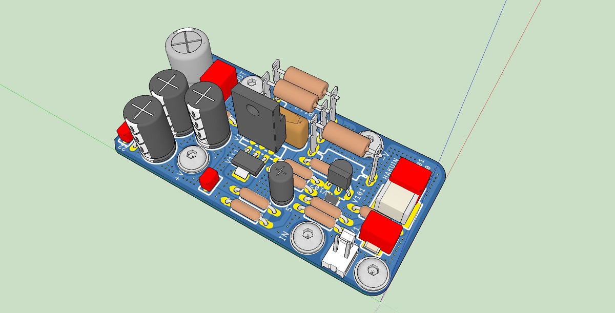
3D render of board with both types of actives installed:
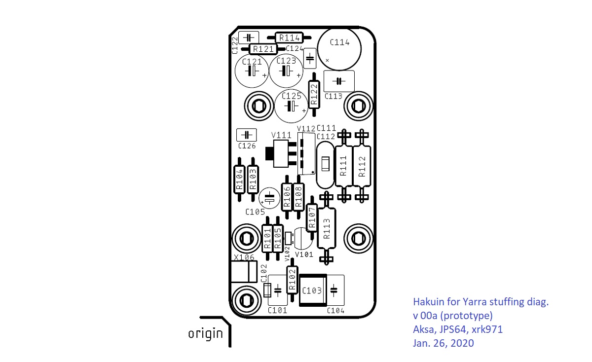
Stuffing Diag:
I have found that the (huge) 2.2uF PET capactor in SMT provides and excellent sound for the input cap. For output coupling duties, you can use what is on the Yarra MB, or the recommended 1000uF Panasonic OSCON cap.
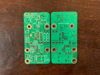
The PCBs are now just in. Looks like an easy and fun build if you want to hear what this sounds like on the Yarra or M2X.
Attachments
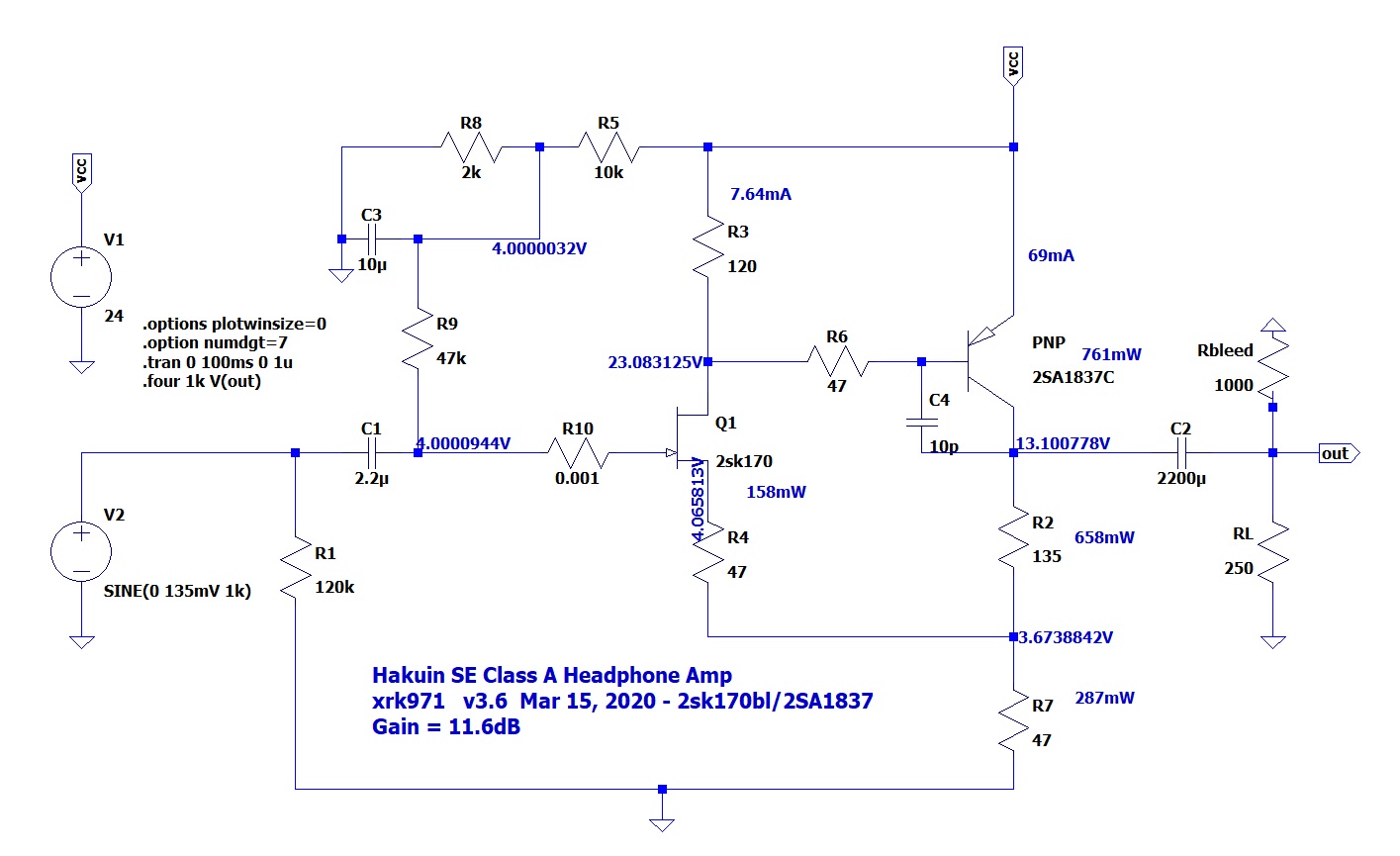
It turns out that these values are also ideal for 2SK170BL input JFETs. The LTSpice sim shows a dop in replacement. Bias current goes up about 10mA but the THD and distortion profile stays the same.
FFT for 1Vpp into 250ohms:
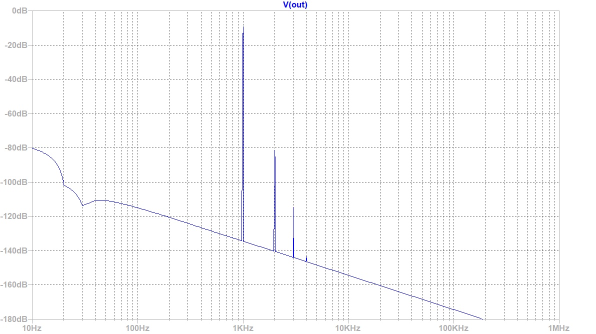
FFT for 1Vpp into 250ohms:
Attachments

Last edited:
It turns out that these values are also ideal for 2SK170BL input JFETs. The LTSpice sim shows a dop in replacement. Bias current goes up about 10mA but the THD and distortion profile stays the same.
Thanks for running the LTSpice sim X!
I will give the Hakuin the full Toshiba treatment 😀
Yarra main board GB#2 list
Name Number of Board Country
xrk971 5 USA
32y0 1 AUS
redjr 1 USA
Gregetzof 1 USA
_____________
We need 7 more for 15 boards
Name Number of Board Country
xrk971 5 USA
32y0 1 AUS
redjr 1 USA
Gregetzof 1 USA
_____________
We need 7 more for 15 boards
Hi X,
I am interested in the Hakuin db for the Yarra. Can you confirm that for the input FET - we only need to load the Toshiba 2SK170BL at V101 and ignore V102. I notice the schematic says 1 or the other for V101 or V102.
I will also use all original Toshiba's like Vunce has mentioned.
When do you expect to have these in your store for sale? I will order these and some SFP pcb's at the same time.
Gary..
Hi Gary,
The Hakuin DB's are now available on my shop here:
Hakuin DB for Yarra | Etsy
You only need to use one JFET, either 2SK209BL ot 2SK170BL, so ignore TH pads if using SMT and vice versa. For the BJT, the 2SA1837 is the best of course, but can also use TTC004B, or the small DZT5401 SMT option. Depending on which option you use, the resistor setpoints are different. However, same settings for 2SA1837 with either 2SK209BL or 2SK170BL. So only 2 transistors needed per amp module (1 JFET and 1 BJT).
Thanks X, just to confirm the price shown is per pcb and for stereo - one needs to buy 2 off.
Have the schematic where you have shown the resistor values for all Toshiba's.
Have the schematic where you have shown the resistor values for all Toshiba's.
Thanks again X.
Looking at the schematic, R108 is shown as 4.7 ohm, but on the sim (V3.6) of 15th March, the resistor (R6) is shown as 47 ohm. What should it be?
Also resistors R111 and R112 are shown as 300 ohm each (in parallel) for the 2SA1837, but on the sim the resistor R2 is shown as 135 ohm - so I assume with the 2 resistors in parallel on the pcb one would use 2 off 270 ohm to give the resistance as 135ohm.
Are you going to do a BOM for this pcb?
R108 should be 4R7, sorry for the typo. I mentioned that since I did not have 300ohm resistors, I used two 270ohms in parallel for equivalen 135ohms and it works fine.
Yes, Vunce is working on a Mouser shopping cart right now based on the schematic. Mouser doesn't have any 2SK209BL's in stock. Digikey has very few BL's left.
I might have to run a simulation with the 2SK209GR's and see what we have to do with the resistors to get them to work.
Yes, Vunce is working on a Mouser shopping cart right now based on the schematic. Mouser doesn't have any 2SK209BL's in stock. Digikey has very few BL's left.
I might have to run a simulation with the 2SK209GR's and see what we have to do with the resistors to get them to work.
- Home
- Group Buys
- The YARRA Preamplifier/HPA for Melbourne DB Group Buy