Hi Thompsontechs,
Thank you for the offer! I might have to take you up on it if we don't have some more people interested in having a GB#2 for the main board set. I'll let you know.
Cheers,
X
Thank you for the offer! I might have to take you up on it if we don't have some more people interested in having a GB#2 for the main board set. I'll let you know.
Cheers,
X
New Yarra Preamp Module: Hakuin JFET/BJT CFP SE Class A
After hearing how good the Hakuin sounds as a headphone amplifier over in this thread, I knew that this just has to be offered as a preamp/HPA module for the Yarra. The sound is incredible - extremely resolving but non-fatiguing. It has immense bass clarity and great dynamics. Recording details are brought out clearly and the soundstage is accurate, wide and impressive. The topology was developed by Hugh several years ago as a possible variant for my Pocket Class A (but never released), and which has since then, transformed into the new high tech Hakuin headphone amplifier with LiPo battery management, DC-DC step up, low noise LDO, and battery level meter witha 3D printed case.
Here is the Hakuin HPA under listening tests (PSU sub section still to be built):
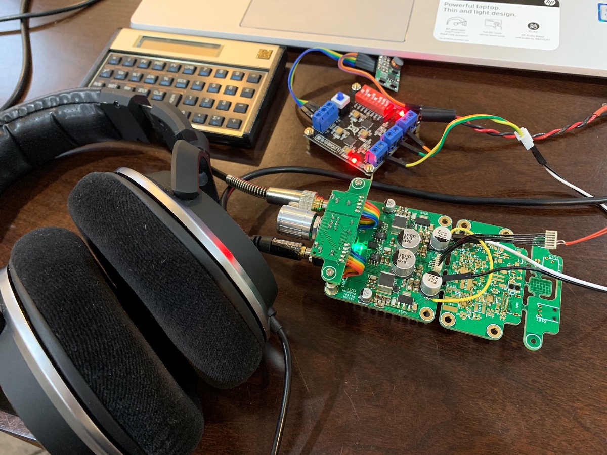
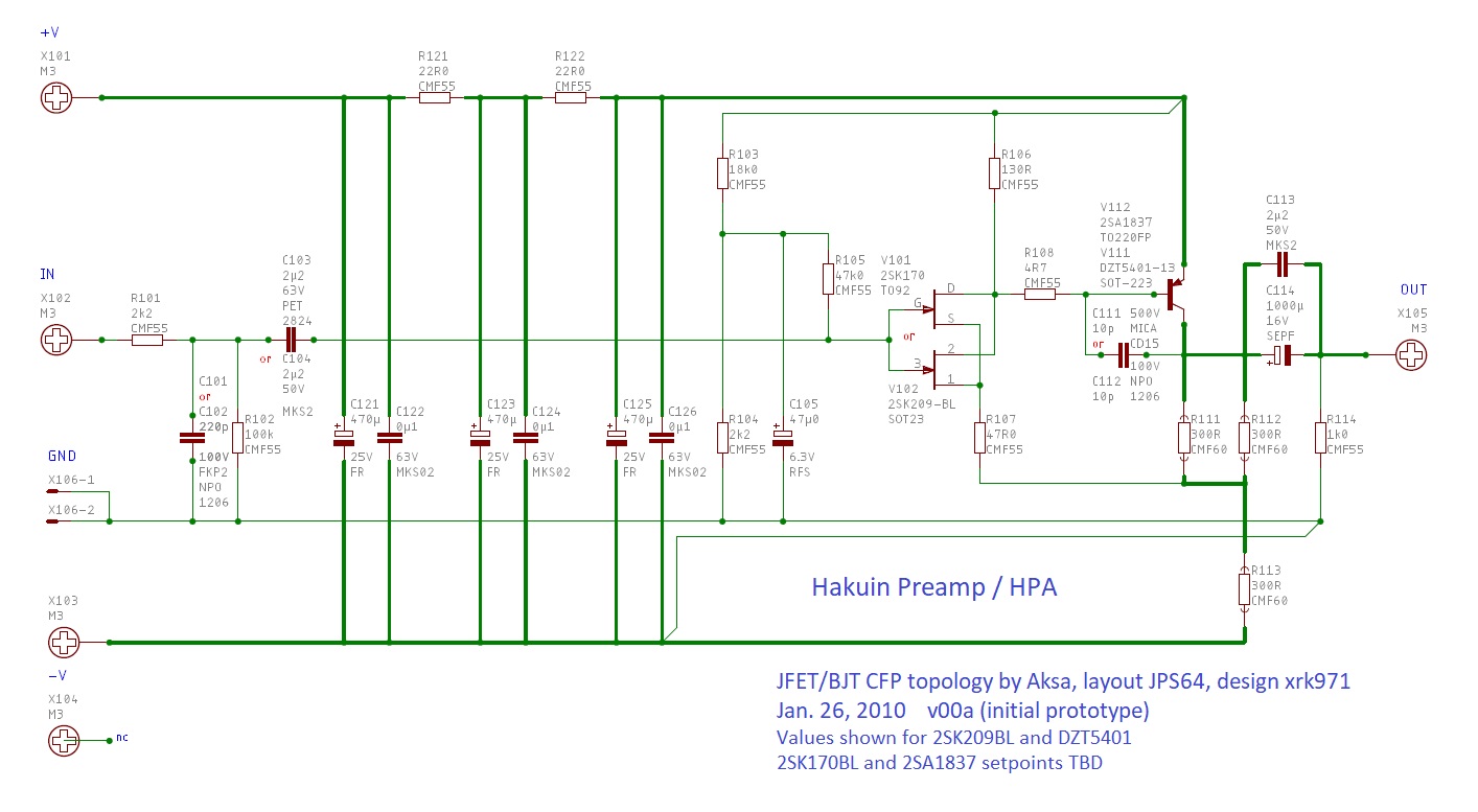
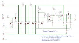
The circuit is about as simple as it gets - an N channel JFET as the master driving a PNP BJT as the slave running at a good bias current in SE Class A operation. The original one I made used a BF862 and 2SA1837. For all SMT assembly on the Hakuin HPA, I chose the still available 2SK209BL for the JFET and the DZT5401 BJT which can handle some power. For the Yarra module however, we are also adding the option of using the Toshiba Duo of 2SK170BL and the 2SA1837 - both now unobtanium, but perhaps the pairing of the finest JFET and BJT ever made or ever will be made for audio in a glorious union. I still need to calculate the resistor setpoints for the 2SK170BL and 2SA1837, but the 2SK209BL and DZT5401 as shown in this schematic are good to go. Gain is about 12dB and btw, this could be used as a great input module on the M2X power amp. Design is for 24v single rail, so perfectly compatible with upper rail of a 25w Class A amp.
A big thanks to Hugh for the circuit and inspiration, and big thanks to JPS64 for the wonderful layout!
The CFP (Sziklai pair) topology is very fast, and I believe this is where the extra resolution comes from. I am looking to building this with the 2SK170BKL and 2SA1837.
Schematic:
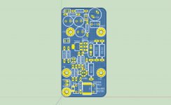
PCB top:

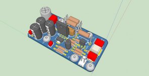
3D render of board with both types of actives installed:

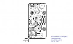
Stuffing Diag:

I have found that the (huge) 2.2uF PET capactor in SMT provides and excellent sound for the input cap. For output coupling duties, you can use what is on the Yarra MB, or the recommended 1000uF Panasonic OSCON cap.
After hearing how good the Hakuin sounds as a headphone amplifier over in this thread, I knew that this just has to be offered as a preamp/HPA module for the Yarra. The sound is incredible - extremely resolving but non-fatiguing. It has immense bass clarity and great dynamics. Recording details are brought out clearly and the soundstage is accurate, wide and impressive. The topology was developed by Hugh several years ago as a possible variant for my Pocket Class A (but never released), and which has since then, transformed into the new high tech Hakuin headphone amplifier with LiPo battery management, DC-DC step up, low noise LDO, and battery level meter witha 3D printed case.
Here is the Hakuin HPA under listening tests (PSU sub section still to be built):
The circuit is about as simple as it gets - an N channel JFET as the master driving a PNP BJT as the slave running at a good bias current in SE Class A operation. The original one I made used a BF862 and 2SA1837. For all SMT assembly on the Hakuin HPA, I chose the still available 2SK209BL for the JFET and the DZT5401 BJT which can handle some power. For the Yarra module however, we are also adding the option of using the Toshiba Duo of 2SK170BL and the 2SA1837 - both now unobtanium, but perhaps the pairing of the finest JFET and BJT ever made or ever will be made for audio in a glorious union. I still need to calculate the resistor setpoints for the 2SK170BL and 2SA1837, but the 2SK209BL and DZT5401 as shown in this schematic are good to go. Gain is about 12dB and btw, this could be used as a great input module on the M2X power amp. Design is for 24v single rail, so perfectly compatible with upper rail of a 25w Class A amp.
A big thanks to Hugh for the circuit and inspiration, and big thanks to JPS64 for the wonderful layout!
The CFP (Sziklai pair) topology is very fast, and I believe this is where the extra resolution comes from. I am looking to building this with the 2SK170BKL and 2SA1837.
Schematic:
PCB top:
3D render of board with both types of actives installed:
Stuffing Diag:
I have found that the (huge) 2.2uF PET capactor in SMT provides and excellent sound for the input cap. For output coupling duties, you can use what is on the Yarra MB, or the recommended 1000uF Panasonic OSCON cap.
Attachments
Last edited:
Hi Thompsontechs,
Thank you for the offer! I might have to take you up on it if we don't have some more people interested in having a GB#2 for the main board set. I'll let you know.
Cheers,
X
I would be interested in a GB#2.
Ok, great - I will start the Yarra mainboard GB #2 interest list now.
Name Number of Board Country
xrk971 5 USA
32y0 1 AUS
Name Number of Board Country
xrk971 5 USA
32y0 1 AUS
Ok, great - I will start the Yarra mainboard GB #2 interest list now.
Name Number of Board Country
xrk971 5 USA
32y0 1 AUS
redjr 1 USA
Name Number of Board Country
xrk971 5 USA
32y0 1 AUS
redjr 1 USA
Speaking of different output options, I would prefer balanced outputs driven by a transformer rather than an opamp. I saw 3D renderings of such here a while ago, but they didn't seem to make it into fabrication.
I already have a full set of boards and case components, but have held off on building until I can find a good solution for balanced outputs with sufficient voltage to drive an F4.
I already have a full set of boards and case components, but have held off on building until I can find a good solution for balanced outputs with sufficient voltage to drive an F4.
We will look at a Yarra V2 but it’s off in the future. The GB2 I am asking people for interest now is an identical board to what has been shipped thus far. The Yarra layout is not easy to modify as changing one thing moves other things and there are lots of vias to manually add again.
Couple of things we are already looking at:
Balanced in and out but realize that it will mean the balanced goes through a THAT based specific opamp converter. MCU controlled turn on delay and digital volume control, Bluetooth input capability, phono stage input,...
A regulated PSU might be a good idea. For the separate psu I meant that it would be identical - minimal layout work. To make it regulated would be a new board basically
Keep the ideas ideas coming..
X,
Since there has been some talk about a separate PSU, and a Yarra V2 in the future, I'd like to suggest moving the IEC jack off of the PSU PCB. Instead, just have 2 solder pads for AC-in. This would free up some PCB real-estate, making it shorter in length. Most of the enclosures I buy from Asia already come with a cut-out for an IEC jack on the back panel. This arrangement gives the builder more flexibility with the internal layout of the project PCBs and how the AC is routed internally, and desired ON/OFF switch placement on the front panel.
Just my .02 cents. 🙂
Hi Redjr,
We need to keep the PSU board compatible with the Yarra chassis which has a cutout for the IEC. If you want to use in your own chassis with your own IEC, just don't populate the Schurter IEC and use the provided screw terminal AC input connectors already provided. Or you could just solder your wires to where the holes are for the IEC output. Does that work?
Edit: I noticed that the gen 1 PSU has the screw terminal jack for external AC mains input and the new one does not. The new one also has an on-board AC-DC Meanwell switchmode to provide auxilary 12vdc to run other stuff and that will take up some room in the back of the PCB. I suppose we can ask JPS64 to provide some sort of jack for AC mains input then? Probably Faston spades are the lowest profile connectors.
Last edited:
Hi Redjr,
We need to keep the PSU board compatible with the Yarra chassis which has a cutout for the IEC. If you want to use in your own chassis with your own IEC, just don't populate the Schurter IEC and use the provided screw terminal AC input connectors already provided. Or you could just solder your wires to where the holes are for the IEC output. Does that work?
Edit: I noticed that the gen 1 PSU has the screw terminal jack for external AC mains input and the new one does not. The new one also has an on-board AC-DC Meanwell switchmode to provide auxilary 12vdc to run other stuff and that will take up some room in the back of the PCB. I suppose we can ask JPS64 to provide some sort of jack for AC mains input then? Probably Faston spades are the lowest profile connectors.
No worries. I incorrectly assumed V2 would have a redesigned back panel. I can work with any design changes should I use my own enclosure. I was also assuming the PSU would be a separate product with a new form-factor, since you mentioned that would require a new layout. I do like the idea of adding a 12v out as aux power. Don't you hate 'design by committee'! 😀
X, the Hakuin JFET/BJT CFP SE Class A, again looks great! Will it be offered on your Esty page?
Has anyone found a part number for the resistor stand-offs the JPS64 has in a lot of his 3D renderings? I know one can achieve similar results by soldering the resistors elevated off the PCB by using the leads alone for cooling purposes. Is their another reason for using the stand-offs?
Has anyone found a part number for the resistor stand-offs the JPS64 has in a lot of his 3D renderings? I know one can achieve similar results by soldering the resistors elevated off the PCB by using the leads alone for cooling purposes. Is their another reason for using the stand-offs?
Yes, I will have it on Etsy soon - need to place the order for the PCBs. The standoffs allow easier swapping of resistors.
For the small resistors like CMF55 or CMF60 you can use this one:
1036 Keystone Electronics | Mouser Deutschland
JP
1036 Keystone Electronics | Mouser Deutschland
JP
The mouser BOM is showing the BC560CTA is obsolete.
What can we substitute?
Mouser Electronics Canada
What can we substitute?
Mouser Electronics Canada
Any small signal TO92 PNP with same pin out should work. If you have to, cross legs on 2N5401 or KSA992.
For the small resistors like CMF55 or CMF60 you can use this one:
1036 Keystone Electronics | Mouser Deutschland
JP
Slotted Turret Lugs seems to be another solution:
H2073Z01 Harwin | Mouser
New Yarra PSU with LT4320 and TPS7A4xx LDO
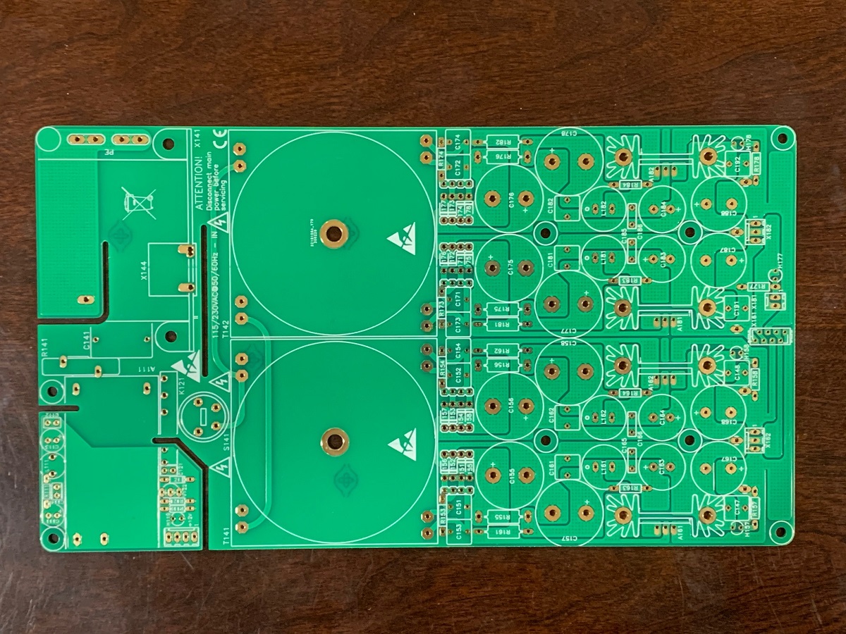
JPS64 has designed a very nice new PSU for the Yarra which now can be used as a universal ultra-low noise power supply for preamp/headphone amps. I just received the new verification boards today and they look very nice. The boards follows very much the same physical outline of the original PSU but now adds several new features which some users may like:
1. the option (1A 1N400X axial diodes can still be used) of using a micro sized mezzanine riser LT4320 active bridge rectifier to really reduce diode bridge switch noise. It makes diode ringing and snubbing a thing of the past.
2. A voltage regulator following the LM78xx/79xx TO-220 footprint. So you can use conventioanal voltage regulators or you can use special ultra-low noise TPS7A47 or TPS7A33 low dropout regulators (LDO's) to give your amp a fixed and very low noise supply rail (up to 1A). These are availble preamde from eBay or Aliexpress, or you can build your own with 6 parts using JPS64's custom adapter board.
3. An independent 12v SMPS with CLC filter connected to the mains input to provide power for your auxiliiary accessories like an MCU, relays, etc.
4. 3-pin Molex KK connectors for running the power to your preamp project if you don't want to use the origianal flat cable connector.
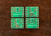
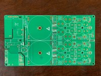
Here is the mainn board and optional LT4320 bridge and TPS7Axx TO-220 adapter boards.
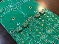
Main PSU PCB:
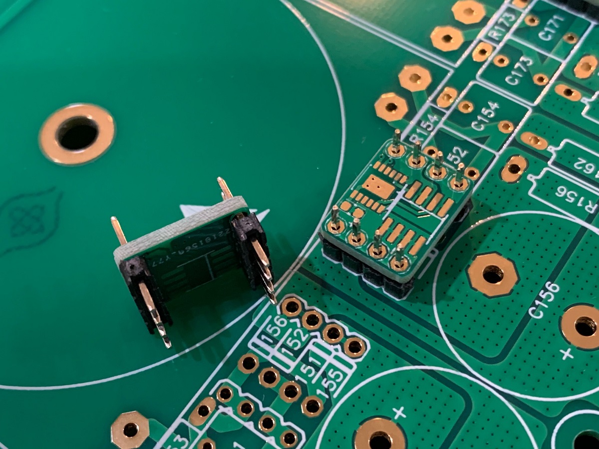
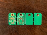
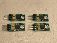
Closeup of the new micro LT4320 bridge boards (note that one MOSFET mounts on bottom side):

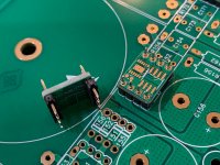
With optional LT4320 active bridges installed:

Closeup of LT4320 bridges above the mainn PSU:
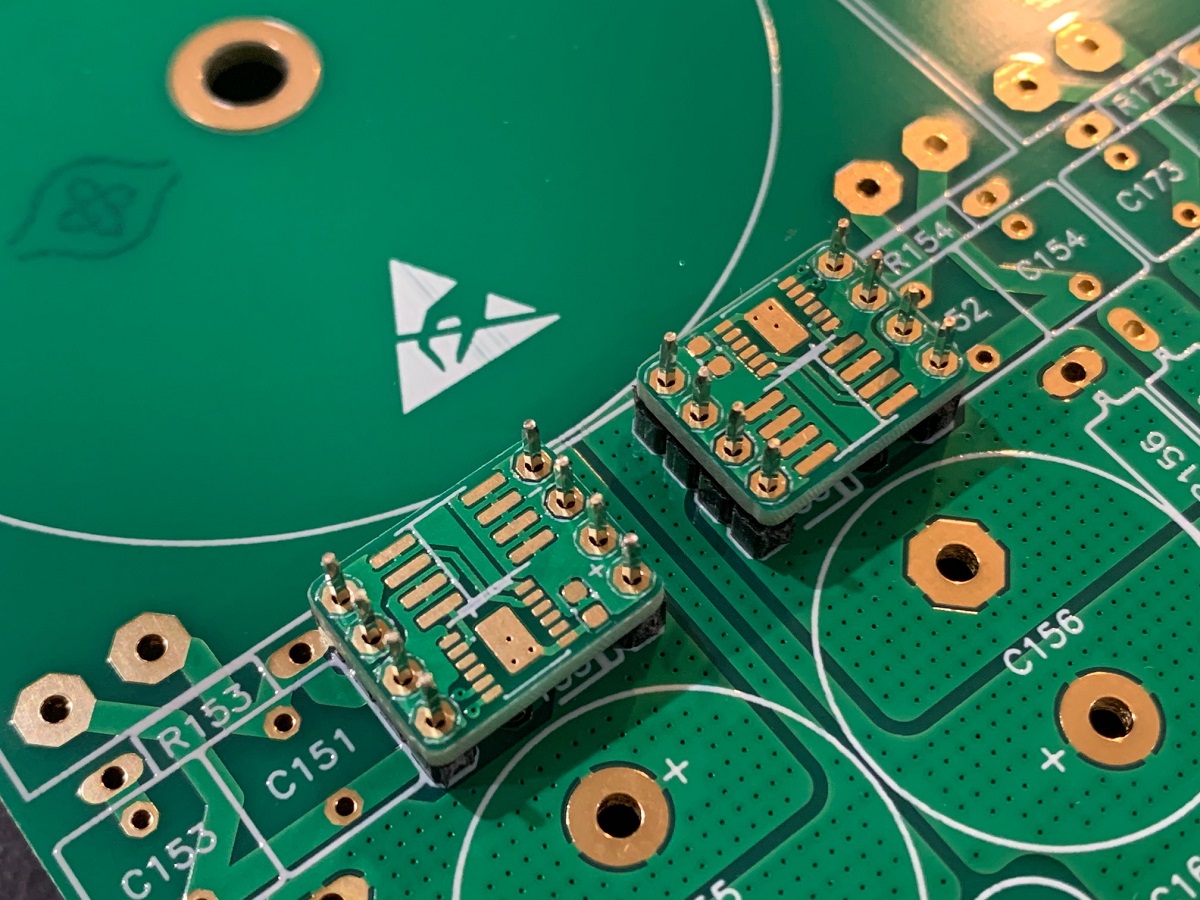
Closeup of LT4320 bridges and PCB mezzanine riser pins:
Custom TPS7Axx boards for the LDO's:

JPS64 has designed a very nice new PSU for the Yarra which now can be used as a universal ultra-low noise power supply for preamp/headphone amps. I just received the new verification boards today and they look very nice. The boards follows very much the same physical outline of the original PSU but now adds several new features which some users may like:
1. the option (1A 1N400X axial diodes can still be used) of using a micro sized mezzanine riser LT4320 active bridge rectifier to really reduce diode bridge switch noise. It makes diode ringing and snubbing a thing of the past.
2. A voltage regulator following the LM78xx/79xx TO-220 footprint. So you can use conventioanal voltage regulators or you can use special ultra-low noise TPS7A47 or TPS7A33 low dropout regulators (LDO's) to give your amp a fixed and very low noise supply rail (up to 1A). These are availble preamde from eBay or Aliexpress, or you can build your own with 6 parts using JPS64's custom adapter board.
3. An independent 12v SMPS with CLC filter connected to the mains input to provide power for your auxiliiary accessories like an MCU, relays, etc.
4. 3-pin Molex KK connectors for running the power to your preamp project if you don't want to use the origianal flat cable connector.
Here is the mainn board and optional LT4320 bridge and TPS7Axx TO-220 adapter boards.
Main PSU PCB:
Closeup of the new micro LT4320 bridge boards (note that one MOSFET mounts on bottom side):
With optional LT4320 active bridges installed:
Closeup of LT4320 bridges above the mainn PSU:
Closeup of LT4320 bridges and PCB mezzanine riser pins:
Custom TPS7Axx boards for the LDO's:
Attachments
-
 Yarra-PSU-LT4320-Bridge-06.jpg442.6 KB · Views: 1,838
 -
 Yarra-PSU-LT4320-Bridge-05.jpg300.5 KB · Views: 983
 -
 Yarra-PSU-LT4320-Bridge-04.jpg324.9 KB · Views: 531
 -
 Yarra-PSU-LDO-photo-03.jpg474.2 KB · Views: 972
 -
 Yarra-PSU-LT4320-Bridge-02.jpg366.9 KB · Views: 520
 -
 Yarra-PSU-LDO-photo-01.jpg432.1 KB · Views: 540
Last edited:
Fantastic news X!!
The layout is very slick JPS!! I like the LT4320 option and X162/X182 for optional output wiring configuration.
Looks like these beauties will have a new home 😀
Nice work Fellas!

The layout is very slick JPS!! I like the LT4320 option and X162/X182 for optional output wiring configuration.
Looks like these beauties will have a new home 😀
Nice work Fellas!
Attachments
Last edited:
- Home
- Group Buys
- The YARRA Preamplifier/HPA for Melbourne DB Group Buy