Hello Yarra PCA builders,
Vunce has done the hard work of verifying that the following resistor settings work well for the 2SK209GR and 2SK170BL JFETs.
YARRA PCA w/2SK209GR
R121 - 33R
R123 - 47R
This modification drops Yarra voltage from 29v to 21v on the PCA board.
R103 + R104 = 5k4
R105 = 440R
R106 = 1360R
R112 - R115 = 560R each
This setup gives 90mA bias
—————————————
AKSA LENDER w/2SK170BL
Voltage after capMx is 20.5vdc
R103 + R104 = 2K
R105 = 75R
R106 = 680R
R112 - R115 = 560R each
This set up gives 75mA bias
#### also note well, if you jumper the output coupler cap on the PCA board, you need to use the Yarra motherboard output coupling caps. The output bleed resistor needs to be reduced to 680R to prevent high output DC offset.
Change motherboard R126 and R136 to 680R (originally 47k).
On PCA:
C101 - replaced with jumper
C111 - eliminated
C112 - replaced with jumper
R101 - eliminated
Hi X,
I'm will be building two Yarra's. I have both the 15v and 18v trafo's. I also have a stash of 2sk170bl's. Will the R103-106 values work with either Yarra build? One will be a HPA and the other will be a Preamp.
The Korg DB looks awesome! I have the DIY store korg board and tube waiting until I get the Yarra built. This might change up my plans.
Hi TboneAK,
Yes, if you plan on using the BL’s - the resistors show. Will work for either trafo voltage.
Yes, if you plan on using the BL’s - the resistors show. Will work for either trafo voltage.
AKSA LENDER w/2SK170BL
Voltage after capMx is 20.5vdc
R103 + R104 = 2K
R105 = 75R
R106 = 680R
R112 - R115 = 560R each
This set up gives 75mA bias
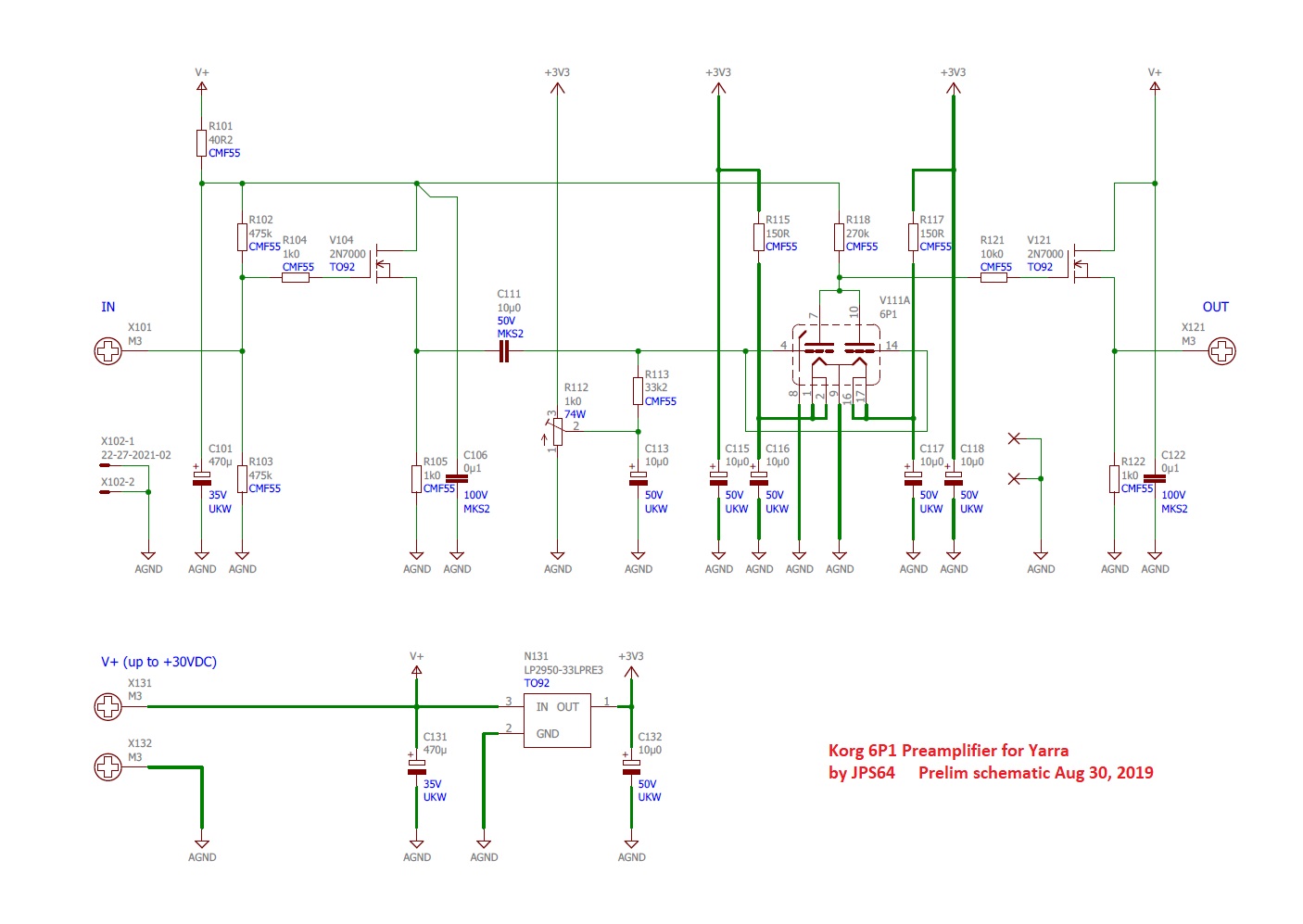
I forgot to mention that the Korg 6P1 preamp circuit was based on Pete Millet’s design (used with permission - thanks, Pete Millet!). It does have a modification to run parallel triodes so the current drive will be more powerful.
Can someone, who has finished building the Yarra Preamp post a pic or two, on how to physically mount the vol pot onto the chassis.
Mine vol pot was aligned properly behind the faceplate, but there is no way I can tighten it to the faceplate. So it's kind of dangling behind but still sings perfectly.
Thanks
Mine vol pot was aligned properly behind the faceplate, but there is no way I can tighten it to the faceplate. So it's kind of dangling behind but still sings perfectly.
Thanks
Can someone, who has finished building the Yarra Preamp post a pic or two, on how to physically mount the vol pot onto the chassis.
Thanks
Hi meanie,
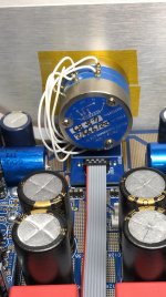
I didn’t feel comfortable leaving the volume pot board un-soldered. I soldered pins to the bottom side of the volume pot board and then soldered that directly to the motherboard to keep close as possible to the MB without touching. Then I soldered jumper wires from the volume pot to the volume pot board and mounted the volume pot to the face plate.
Attachments
Thanks, Vunce.
I was thinking of soldering it directly using those pins as support, but I have not decided which brand of pot that I want to use.
Love the look of your pot, what brand is that?
What is the pot impedance you using?
One questions open to all, what is the sonic significant of using various different pot impedance? example 10k, 50k or 100kohms?
I noticed in valve sets, some uses as high as 500k to 1Mohms resistance.
Sorry for so many questions, I just hope to get the optimum pot for this Yarra Preamp.
Thanks, Vunce.
I was thinking of soldering it directly using those pins as support, but I have not decided which brand of pot that I want to use.
Love the look of your pot, what brand is that?
What is the pot impedance you using?
No prob meanie 🙂
It’s a Penny & Giles 10k pot.
Unfortunately, I don’t think they are made anymore.
I have mostly used 10k pots on my preamps and headphones amps. Sometimes a 50k pot. I think most sources can drive a 10k pot with no issues. Maybe some tube output stages like to drive 1M? Higher input impedance pots pick up RFI noise easier. I think 10k pots tend to be very quiet from EMi/RFI standpoint.
I still haven’t gotten into boutique pots yet so can’t really say - but a decent quality $3 Alps RK09 series has served me well on countless projects.
I have bought a stepped attenuator fitted with SMT resistors. I need to try it out. Although I think the next thing will be a digital pot from Maxim controlled by a WiFi Aduino nano and a phone app.
Last edited:
Count me in for two, as well. With a M2X and two Yarras in the works, why not have all the options for DB’s. 😀
Could someone please tell me the values for R154 and R174 of the Yarra (beside the transformers).
All I can find is TBA.
Also I can't find the WBA18 cct diagram.
All I can find is TBA.
Also I can't find the WBA18 cct diagram.
Last edited:
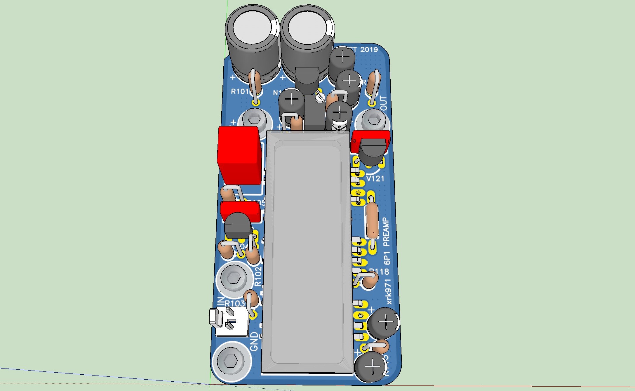
I guess we can start making an interest list for the Korg 6P1 (Pete Millet based) preamp core board.
Meanie - 2 boards - Singapore
TboneAK - 2 boards - USA
Meanie - 2 boards - Singapore
TboneAK - 2 boards - USA
Last edited:
Same as any of the other Yarra preamp core modules - same bolt pattern. You need to provide a connection to GND via the connector. There is a 3.3v regulator for the Korg, the Vcc can be up to 30v so 24v to 25v +ve rail of an M2X is fine. With that said, this remains to be tested.
- Home
- Group Buys
- The YARRA Preamplifier/HPA for Melbourne DB Group Buy