I use 10mm long M3 standoffs myself as shorter ones wont allow two opposing screws to be opposed. I think the case is talk enough for this height.
I used 3/8" 4-40 thread F/F standoffs for the Yarra associated boards - lines up well with the JP modushop case.
For the daughter cards I used 1/4" 4-40 thread M/F standoffs (Zn coated brass) and suitable length SS screws + internal toothed lock washers.
M3 is also good, and probably the design base.
BK
For the daughter cards I used 1/4" 4-40 thread M/F standoffs (Zn coated brass) and suitable length SS screws + internal toothed lock washers.
M3 is also good, and probably the design base.
BK
Can anyone enlighten me on the origin of the BOM values for the (optional) Yarra transformer snubber components? 2.2uF/2.2uF/51.1ohm.
BK
BK
They are rather heavy-handed general WAG snubber values. Ideally, you should tune the values on an O-scope with a fixed cap and a pot with your trafo. Adjust until the ringing goes away. Then replace pot with a fixed resistor. More info here.
They are rather heavy-handed general WAG snubber values. Ideally, you should tune the values on an O-scope with a fixed cap and a pot with your trafo. Adjust until the ringing goes away. Then replace pot with a fixed resistor. More info here.
Understood. I have the Quasimodo jig, but in my build fever I didn't stop to measure the transformers. In retrospect what caught my attention was the 1:1 cap values. Hopefully an upcoming builder can take some measurements and share.
BK
I have placed orders for the boards - it took a few days for them to review the Gerbers and approve them for manufacturing. Hopefully have the boards on about 8 days.
Can anyone enlighten me on the origin of the BOM values for the (optional) Yarra transformer snubber components? 2.2uF/2.2uF/51.1ohm.
If you bring your transformer over to my house in the San Jose metroplex, I will be glad to measure the leakage inductance of each of its secondaries. Then you can use the Hagerman equations to calculate component values for a Hagerman optimum snubber.
Or, with leakage inductance known, you can calculate how good / how rotten is any particular choice of snubbing component values, for example, the ones that you already own.
Or, with leakage inductance known, you can put the whole shebang into a SPICE circuit simulation and pleasure yourself as much as desired.
Thanks, Mark, for your generous offer. I understand the physics, but was unsure how the BOM values were determined. In return I'd be happy to leave my RTX6001 Audio Analyzer with you to play with. However, at this juncture I may not find the courage to desolder the transformers from the PCB! Always a risk of PCB damage there, even with a Hakko desoldering gun. Small components not so much.
BK
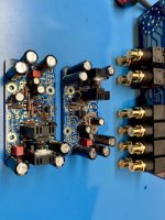
Final Melb cleaning. These actually took a while to build. Even though I used the stuffing guide, I still managed to swap two tombstoned resistors and hand to fix that. If anyone spots an error let me know! Clearance around the specified heatsinks is marginal and best to raise them ~1mm off the board.
BK
BK
Attachments
Dang, I was at the finish line just now and got smoke from the PS.
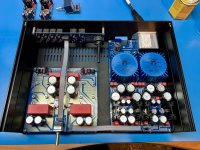
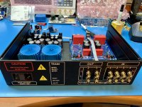
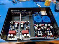
Connected up as shown below (no Melb boards). I had previously tested the PS with Yarra connected by the ribbon cable and all was good, but that was outside case. Since last power-up, I added two LEDs (X181 and H158), PCB mounting screws at X141 for IEC, centered all trimmers.
Burnt the 2.2R at R151 right away. LEDs lit only one side. Fuses didn't blow, but one looks suspect like it was about to go.
I've looked over everything with magnification and don't see any problems or shorts.
Need some direction!
BK
Attachments
I think I found the root cause of the smoked R151!
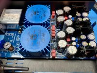
I lied before - I also newly installed standoffs on the Yarra for the Melbourne cards. Everything was within the silkscreen pattern, but the + standoff was somehow shorted to ground. Rearranged the washers and now all seems well. I made a mental note to check all that before powerup and totally forgot. Summit fever I suppose, and a good lesson slow down and take sanity breaks.
Should I suspect any other damage beyond R151 in this scenario?
BK
Is this 1W metal oxide resistor a suitable replacement for metal film R151? I happen to have a bunch from another project.
BK
BK
with all due respect, are you referring to the 2R2 resistor R155? It's more logical that would fail with a positive rail short to ground. A metal oxide resistor would be ok in that location.
Hi BK,
Use small pieces kapton tape above/below the Yarra’s daughter board mounting holes to help insulate the Melbourne’s standoffs from contacting a random via.
Especially on the bottom side where a washer and screw are used. Some of the vias are very close to the mounting holes. 😉
Use small pieces kapton tape above/below the Yarra’s daughter board mounting holes to help insulate the Melbourne’s standoffs from contacting a random via.
Especially on the bottom side where a washer and screw are used. Some of the vias are very close to the mounting holes. 😉
I replaced R155 with a 2.2R MO power resistor from my inventory and continued on. Sorry for the confusion, typo on my part, the charred light blue panasonic resistor was R155 as shown in my previous pics.
In retrospect, it's advisable to use M3 standoffs. They are slightly smaller diameter than 4-40. I looked VERY carefully and didn't see a problem, but the DMM doesn't lie. Or use Vunce's suggestion of some Kapton tape.
All is now good! Looks really great!! Super precision everywhere.
BK
In retrospect, it's advisable to use M3 standoffs. They are slightly smaller diameter than 4-40. I looked VERY carefully and didn't see a problem, but the DMM doesn't lie. Or use Vunce's suggestion of some Kapton tape.
All is now good! Looks really great!! Super precision everywhere.
BK
Attachments

- Home
- Group Buys
- The YARRA Preamplifier/HPA for Melbourne DB Group Buy