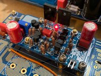
Verification build of WBA18 looking good so far. I am getting about 13mA bias current across the 27R resistor. I made a mistake with a couple of the KSA/KSC combos. Be careful, some groups are the same and some or complementary. The output DC offset is adjustable and started at 4v but easily went to zero. However, very sensitive to temperature. Touching the transistors would make it drift about 0.4v. Stabilized within +/-10mV depending on temp and ambient air flow.
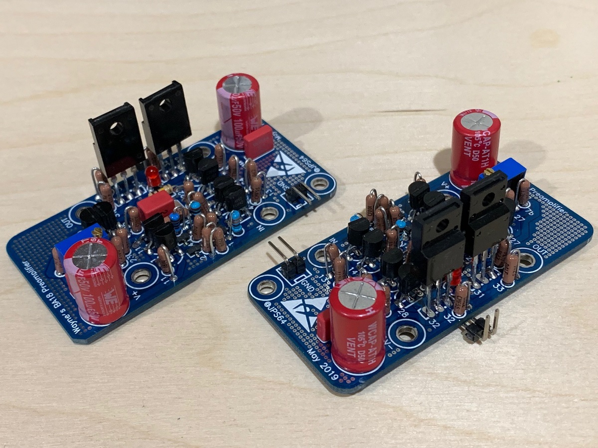
(note that photo shows V121/V122 swapped by mistake):
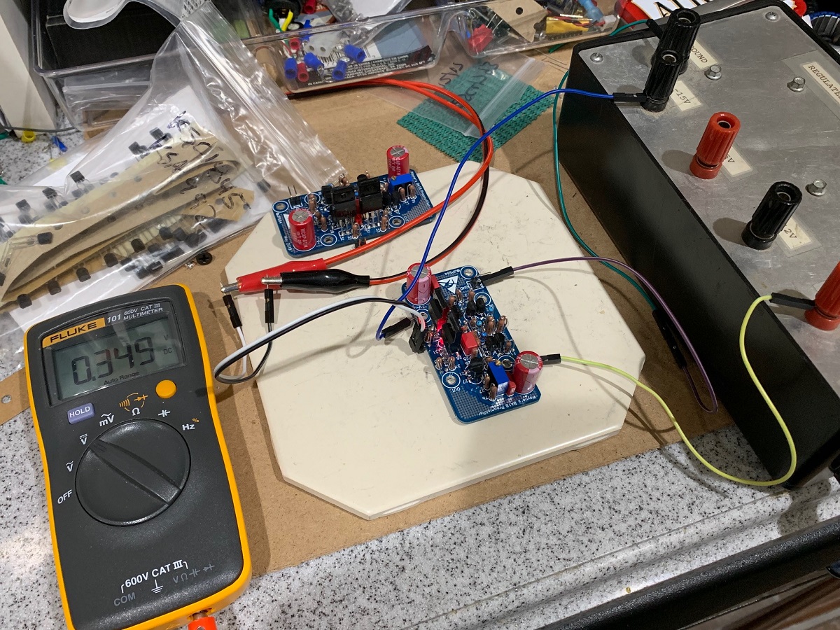
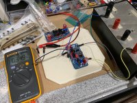
Using lab bench +/-15v power supply to test bias current. Measures 0.349v across R132 (27R) for 13mA:
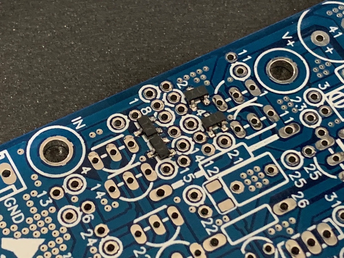
Using solder paste and hot plate on bottom with a hot air pencil on top to solder SMT JFETs (note that this can be performed with a regular fine tip soldering iron and regular solder):
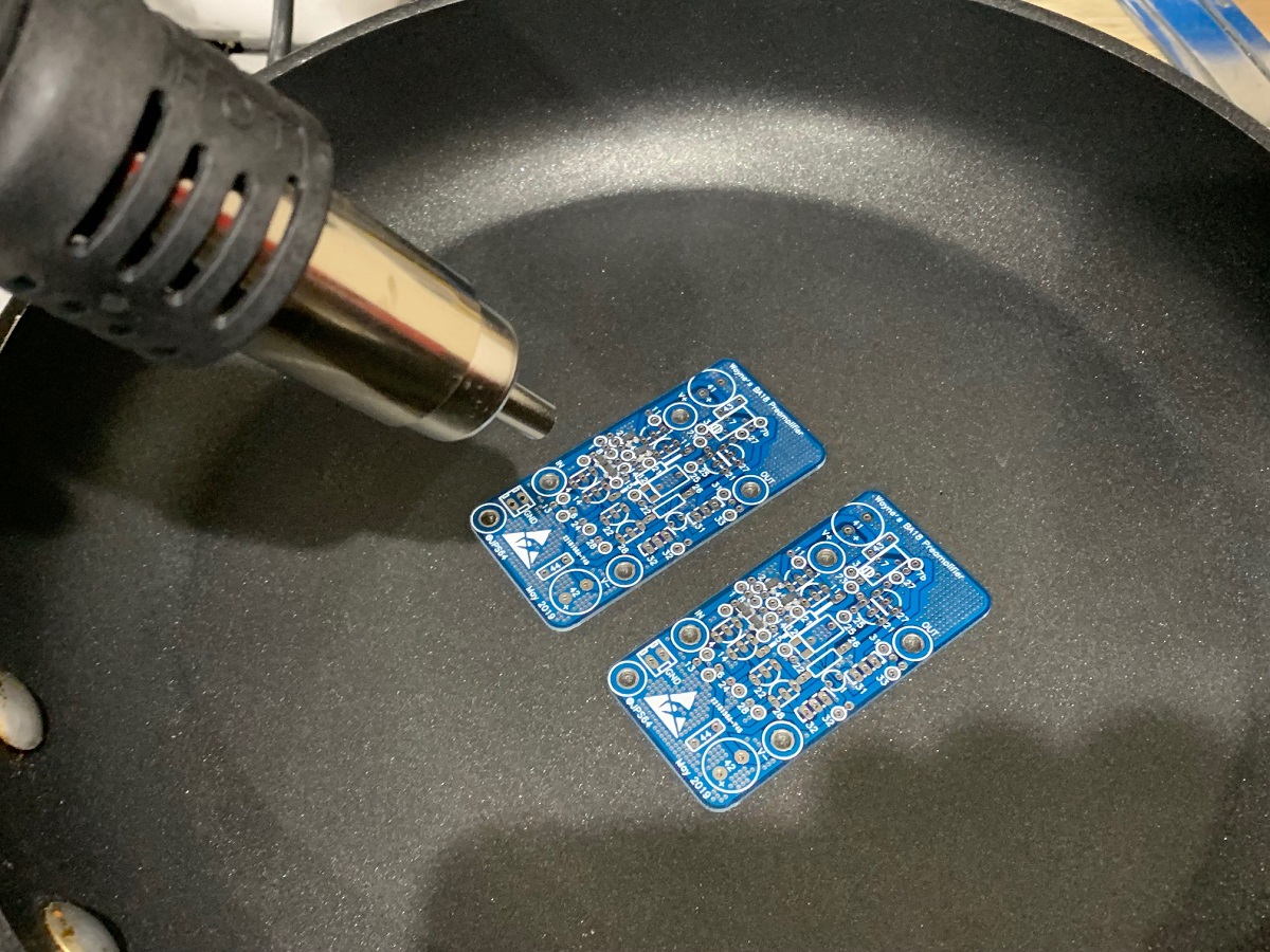
Closeup of JFETs all soldered. Don't forgot to solder the 10pF SMT cap at the same time:
Next step is to listen to it, but I am pretty sure it will work as there was bias current and offset is adjustable.
(note that photo shows V121/V122 swapped by mistake):
Using lab bench +/-15v power supply to test bias current. Measures 0.349v across R132 (27R) for 13mA:
Using solder paste and hot plate on bottom with a hot air pencil on top to solder SMT JFETs (note that this can be performed with a regular fine tip soldering iron and regular solder):
Closeup of JFETs all soldered. Don't forgot to solder the 10pF SMT cap at the same time:
Next step is to listen to it, but I am pretty sure it will work as there was bias current and offset is adjustable.
Attachments


Last edited:
Is there a more up to date Yarra BOM than May 19 in post 1 as that link to Mouser is not a complete BOM.
Somehow I ended up with D44H11 and D45H11 for V167/187 and 168/188
where it should be TIP41c and TIP42c.
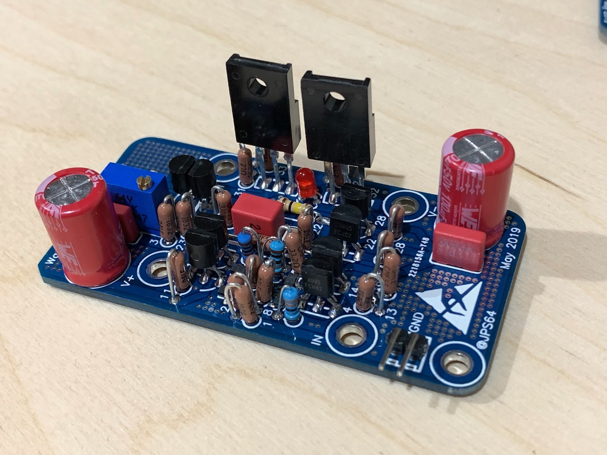
I am pretty confused atm. Also Which caps are to be fitted to the main pcb as it seems impossible to fit 4 caps in the same place around the C122 and C132 area.
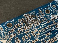
Pics of my main pcb.
Somehow I ended up with D44H11 and D45H11 for V167/187 and 168/188
where it should be TIP41c and TIP42c.
I am pretty confused atm. Also Which caps are to be fitted to the main pcb as it seems impossible to fit 4 caps in the same place around the C122 and C132 area.
Pics of my main pcb.
Attachments

Last edited:
Is there a more up to date Yarra BOM than May 19 in post 1 as that link to Mouser is not a complete BOM.
Somehow I ended up with D44H11 and D45H11 for V167/187 and 168/188
where it should be TIP41c and TIP42c.
I am pretty confused atm. Also Which caps are to be fitted to the main pcb as it seems impossible to fit 4 caps in the same place around the C122 and C132 area.
Pics of my main pcb.
I have soldered in the big red wima 10uFcaps in C122 and C132.
Hi Batty,
All is good - the D44H11/D45H11 are the upgraded “mo’ bettah” transistors for the cap Mx. So that is the latest BOM. What we need to be careful of is that you are not using a shopping cart that got modified by someone.
The apparent tight space where 4-5caps are physically fused into one tiny spot is just there to give you cap rolling options. You can use 1 of those pads. Whether it be a tiny 3.5mm space 10uF Silmic II or a huge oil filled cap - the options are endless. Look at schematic to see what I mean.
I would like to thank the first several folks who have started placing pre-orders on my Etsy shop for the Yarra and WBA18.
Here is what I have so far. When placing orders on Etsy, it would be helpful if you could reference your DIYA handle so I can track vs interest list. -Thanks
Batty - 2 WBA18
Arthur - 3 Yarra w/ 6 WBA18
Md_stryker - 1 Yarra w/ 2 WBA18 + 2 Mels (credit)
Here is what I have so far. When placing orders on Etsy, it would be helpful if you could reference your DIYA handle so I can track vs interest list. -Thanks
Batty - 2 WBA18
Arthur - 3 Yarra w/ 6 WBA18
Md_stryker - 1 Yarra w/ 2 WBA18 + 2 Mels (credit)
Hi Batty,
All is good - the D44H11/D45H11 are the upgraded “mo’ bettah” transistors for the cap Mx. So that is the latest BOM. What we need to be careful of is that you are not using a shopping cart that got modified by someone.
The apparent tight space where 4-5caps are physically fused into one tiny spot is just there to give you cap rolling options. You can use 1 of those pads. Whether it be a tiny 3.5mm space 10uF Silmic II or a huge oil filled cap - the options are endless. Look at schematic to see what I mean.
Thanks X, I soldered in the WIMA 10uF 100v caps, I bought all of them 🙂.
Do the D44H11 replace the TIP41c and the 45 the 42?
WBA18 Playing Music - Fully Verified Now
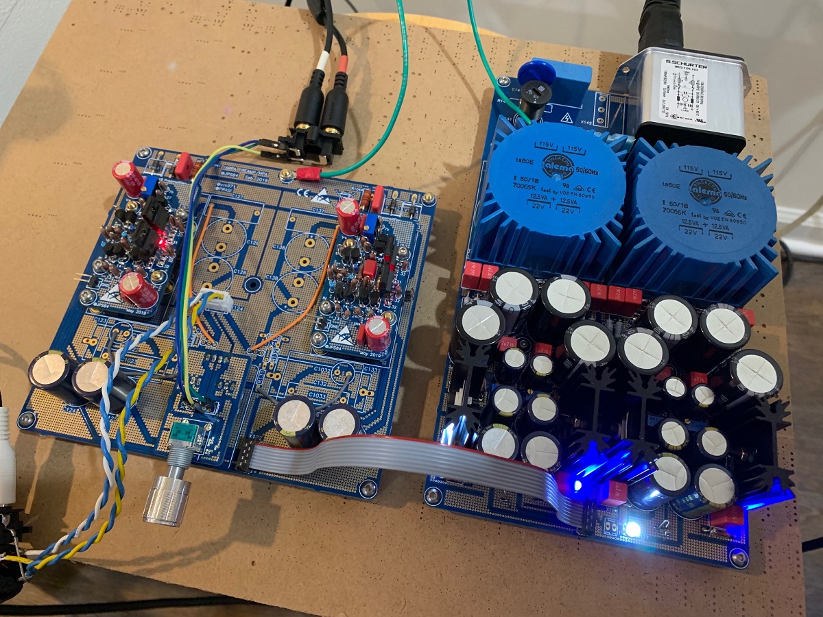
I installed the WBA18's on my current Yarra motherboard with +/-30v power supply. Fired it up and bias current stabilized to essentially same value on both channels at 0.387v across 27ohms or 14.3mA. DC offset is touchy but setable within 10mV drift up and down due to ambient air flow across V121/V127 - which are running quite hot and toasty (circa 70C+). The main outputs (2SA1837 and 2SC4795) are about 50C. If you touch V121/V127, the cooling effect of your finger will send DC offset to drift by about 100mV, and then it slowly stabilizes again. Probably +/-30V rails are too much (although it will work for a while). In reality, transistors can opearate here for a while, no problem.
I am using it to drive a 0dB gain power amp stage (a MOAMOFO) so need all the gain I can get - so I replaced R121 (nominally 10k) with a 1k metal thin film for G=(27.0+1.0)/1.0=28.9dB. It works just fine here and the sound is very nice. No noise issues or anything. Although I have not put an O-scope across it yet to check for oscillatons at this high of a gain setting. The stock setting is only 11.4dB.
For those of you who may want circa 20dB or 22dB gain, that should not be an issue at all. Using R121=2k7 will get you 20.8dB - a moderate gain that some people may like.
Will listen some more but initial impressions are that it is a nice sounding preamp and capable of quite some voltage swing as I am driving a 0dB amp right now to some pretty good and loud levels.
I think these boards are ready to go to production once JPS64 adds a few solder pads for some voltage monitor probe pins across R132 to check the bias current.
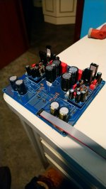
Closeup as mounted in Yarra:

Checking bias current on both channels:
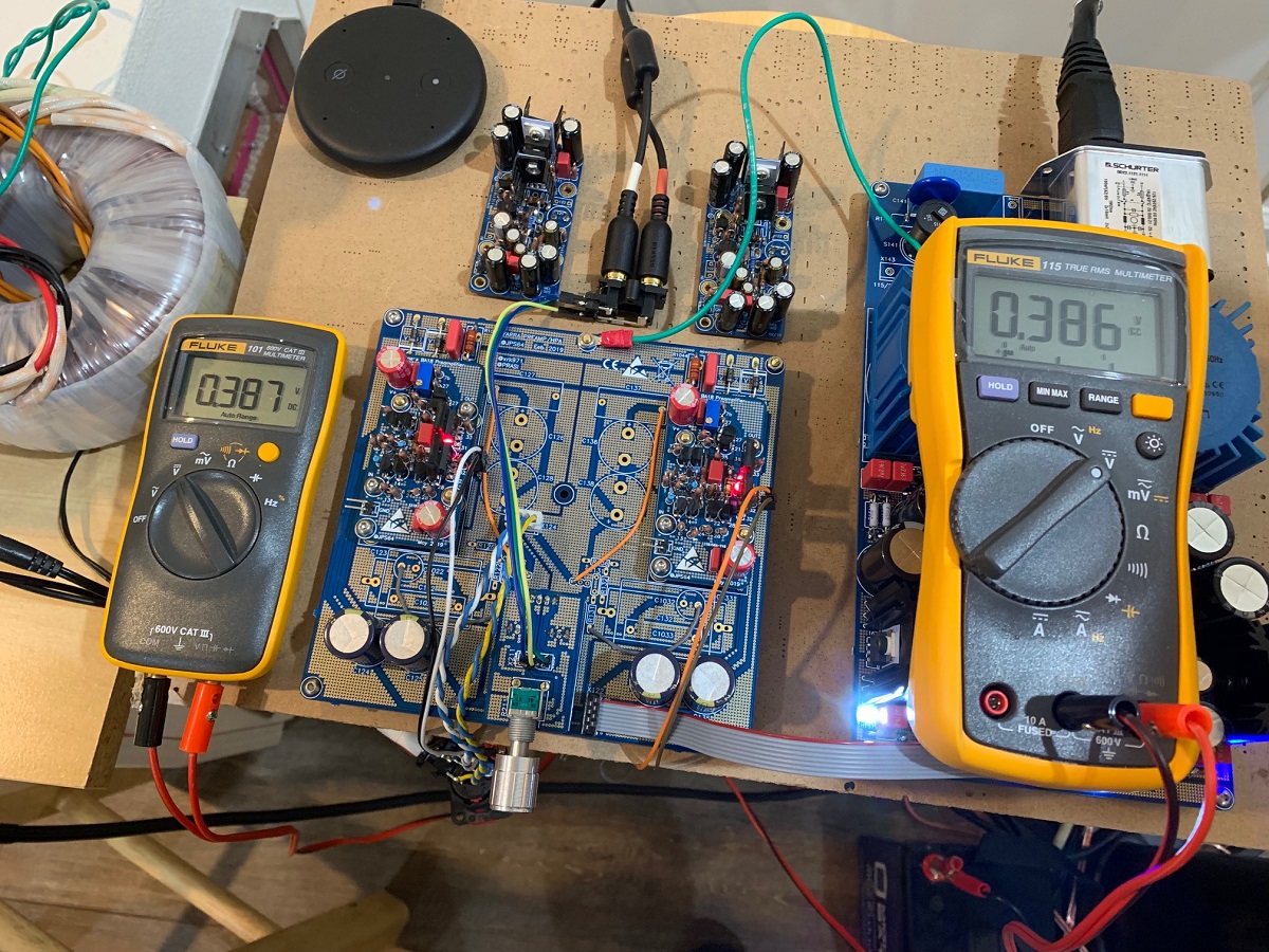
Listening to it...:
I installed the WBA18's on my current Yarra motherboard with +/-30v power supply. Fired it up and bias current stabilized to essentially same value on both channels at 0.387v across 27ohms or 14.3mA. DC offset is touchy but setable within 10mV drift up and down due to ambient air flow across V121/V127 - which are running quite hot and toasty (circa 70C+). The main outputs (2SA1837 and 2SC4795) are about 50C. If you touch V121/V127, the cooling effect of your finger will send DC offset to drift by about 100mV, and then it slowly stabilizes again. Probably +/-30V rails are too much (although it will work for a while). In reality, transistors can opearate here for a while, no problem.
I am using it to drive a 0dB gain power amp stage (a MOAMOFO) so need all the gain I can get - so I replaced R121 (nominally 10k) with a 1k metal thin film for G=(27.0+1.0)/1.0=28.9dB. It works just fine here and the sound is very nice. No noise issues or anything. Although I have not put an O-scope across it yet to check for oscillatons at this high of a gain setting. The stock setting is only 11.4dB.
For those of you who may want circa 20dB or 22dB gain, that should not be an issue at all. Using R121=2k7 will get you 20.8dB - a moderate gain that some people may like.
Will listen some more but initial impressions are that it is a nice sounding preamp and capable of quite some voltage swing as I am driving a 0dB amp right now to some pretty good and loud levels.
I think these boards are ready to go to production once JPS64 adds a few solder pads for some voltage monitor probe pins across R132 to check the bias current.
Closeup as mounted in Yarra:
Checking bias current on both channels:
Listening to it...:
Attachments


Keep up the good work X - do you ever sleep?
A quick question, looking at post #551 on page 56 showing a photo of the bare Melbourne and WBA18 daughter boards, the Melb PCB has a much wider gold plated land around the signal and power supply mounting holes compared to the WBA18. Why is this different I wonder.
I would like to see the WBA 18 PCB being the same around these signal carrying and power supply screw mounting holes as shown for the Melb. DB's, for long term reliability if possible at this late stage.
Hi Gary,
I actually have been sleeping a lot more lately - up early today. 🙂
I asked JPS64 to make the contact ring around the bolt holes bigger too - should not be a problem.
I actually have been sleeping a lot more lately - up early today. 🙂
I asked JPS64 to make the contact ring around the bolt holes bigger too - should not be a problem.
Considering your comments re thermal drift in post #592 above and temps on the 2 output transistors, would a short piece of copper or aluminium flat strip bolted to both output devices help with some thermal compound. As they are fully insulated, this would be easy to do and they are both in line.
This would keep them in thermal equilibrium and also help to lower their operating temperature acting as a small heat sink.
Would be interested in your thoughts.
Even the smaller active devices could be tied together with a small cable tie with a dab of good quality thermal grease between them or heat shrunk together again with some thermal compound between them.
I use a very good quality Thermal Compound - Arctic MX-4. It does not cure and has very long thermal life and you only need a very thin smear on the device, made by a German company and conveniently available in a small 4 gram syringe - so easy to apply to small signal devices right up to large TO-3 metal can output devices.
It's not the big outputs that cause the DC drift, it's mostly the little TO92's. Certainly thermal compound to tie them together would be good and piece of shrink tube over them will probably help. However, for running a large +/-30v supply, I would leave them bare and standing up high and proud for more air cooling. I mounted these a bit low thinking they would look nice with the TO92's the same height as the rest of the parts.
The TO22 (or TO126 if using TTA and TTC's) don't get too warm if you were running +/-18v.
But the idea to use thermal compound to tie the small TO92's together should reduce thermal drift.
The TO22 (or TO126 if using TTA and TTC's) don't get too warm if you were running +/-18v.
But the idea to use thermal compound to tie the small TO92's together should reduce thermal drift.
Will take note of your comments X, when loading the boards, I always tend to leave the small signal TO92 type components sitting high.
Looks like the Mouser BOM that Vunce created and kindly shared has been corrupted again.
Mouser Electronics
-Michael
Mouser Electronics
-Michael
Last edited:
I thought that if we saved something as a "Project" on Mouser's website, it preserves it? Sorry to hear about the broken Shopping Cart/BOM. As a DIY project, we must also put some elbow grease into this and compare with the published text of the BOM.
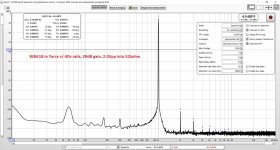
I just got a chance to measure the WBA18 as a preamp driving 2.0Vpp into a 52kohm load. It has a very nice harmonic profile that is 2nd harmonic dominant and lower 3rd harmonic. I think folks will find that this sounds very nice and non-fatiguing. Similar in profile to the Melbourne actually (but using 9 more transistors).
This is with the 2ppm 1khz reference oscillator source and Focusrite 2i4 and no attenuator - driving the input to the 2i4 directly (hence 52k impedance). It has quite a bit of an elevated DC noise floor that results from the sensitivity to therml drift - this preamp might benefit from an AC input coupling cap and output coupling cap to remove some of that lower frequency noise. Since I have a rather high 29dB gain, it is also amplifying that DC drift/noise I think.
Attachments
- Home
- Group Buys
- The YARRA Preamplifier/HPA for Melbourne DB Group Buy