If anyone wants to get rid of his BAL-BAL amplifier,kit or PCB, I'm interested 🙂
What I am doing is using two SE-SE, OPC said a few pages ago that this is a good alternative for those who couldn't get the bal-bal boards.
I would second what regal just posted. You'd actually get a little more voltage swing out of that arrangement, and possibly slightly better overall performance. I know there are a lot of rework SE-SE PCB's (some people have like 8 of them) so I'm sure you could score two of those.
I would offer something up, but I honestly don't have a single board left except my personal one!
Cheers,
Owen
I would offer something up, but I honestly don't have a single board left except my personal one!
Cheers,
Owen
difference LME49600, 49610, LMH6321
Whats the difference between LME49600, LME49610, LMH6321?
Whats the difference between LME49600, LME49610, LMH6321?
I suppose there will be no more group buys, it's a shame, because it looked very interesting... 🙁
Just out of curiosity, the SE-SE version of the wire would have been able to drive my AKG K1000s ?
I am interested too, could drive a SE version the K1000?
The K1000 have 120 OHM, but need some voltage 😱
PS: Today I use a GSP Solo (use only single 15V power), with an adaptor cable, but cannot drive them very loud.
Whats the difference between LME49600, LME49610, LMH6321?
Between LME49600, LME49610 only
LME49600 - High Performance, High Fidelity, High Current Audio Buffer
BW pin floating 110MHz (typ)
BW connected to VEE 180MHz (typ)
LME49610 - High Performance, High Fidelity, High Current Audio Buffer
BW pin floating 120MHz (typ)
BW connected to VEE 200MHz (typ)
are this measurable/hearable?
Which the better choice?
You missed a difference. check the rail voltages.
LME49600 -> +/-18V
LME49610 -> +/-22V
IF you are willing to upgrade other components on the board and take more than 18V from your power supply you get a few more volts swing on the output. Are your headphones performance limited by voltage? (rhetorical question that after you have answered will give you the answer you are looking for)
If you take the time to check the schematic you'll realise that some of your options for BW aren't valid.
You missed a difference. check the rail voltages.
LME49600 -> +/-18V
LME49610 -> +/-22V
Using LME49860NA for frontend this amp should be AKG K1000 (not in bridging mode - using a jack to XLR adapter) ready.
http://www.national.com/images/pf/LME49610/30042540.jpg
If you take the time to check the schematic you'll realise that some of your options for BW aren't valid.
It was only a quick check 🙄
PS: I am searching for a PCB about - using no SMD parts.
with such specific needs i'm afraid youre going to have to make it yourself.......
I must search for the smd version and its EAGLE files.
I must search for the smd version and its EAGLE files.
It may be faster to start working on your own than search for something that isn't available...
As qusp said, you're not really looking for anything to do with this thread.
I think he's looking to convert it to through hole and changing a chip? It does sound like it'd be better to just start fresh at that point.
I think he's looking to convert it to through hole and changing a chip? It does sound like it'd be better to just start fresh at that point.
sounds like hes looking for a magic PCB as well, because they are so simple to design these days
It's not pretty, but it'll work until someone makes something better.
It uses the (similar) TI BUF634 in place of the NS LME496x0. If you don't like that, just rename the component in your schematic/board. 😉
There's also some additional stuff in it, like the OPA1632 and virtually all Neutrik XLR pinouts. But the latter can also be had from the official CadSoft libraries.
Attachments
Last edited:
Input over voltage protection (OVP) with schottky diodes or 2N3904?
I'm curious if you guys (and hopefully OPC too) can comment on using diodes to protect The Wire (BAL-SE) from input overvoltage from upstream gear with higher rails, which could be accidentally (by human error) turned up very loud, and therefore be capable of higher output voltages.
There are a few documents outlining how this might be possible (such as this app note from Analog Devices), but actual implementations seem oddly rare. The general consensus seems to be low-leakage schottky diodes such as BAT-85 (or even 2N3904 wired as a diode using just CB and leaving the emitter disconnected). There are also special devices that exist for this purpose such as the ADG465, but the data sheet mentions nothing about distortion, and the ADG465 isn't popular on this forum, turning up exactly 0 (zero) times after a quick search!
So is it possible to maintain the ultra-high performance of the Wire, maintain the headroom, and somehow have trouble-free input over voltage protection? Attached is what I think might work, but I'm unsure about distortion...
PS it's at times like these I wish I had a super AP test rig 🙂
I'm curious if you guys (and hopefully OPC too) can comment on using diodes to protect The Wire (BAL-SE) from input overvoltage from upstream gear with higher rails, which could be accidentally (by human error) turned up very loud, and therefore be capable of higher output voltages.
There are a few documents outlining how this might be possible (such as this app note from Analog Devices), but actual implementations seem oddly rare. The general consensus seems to be low-leakage schottky diodes such as BAT-85 (or even 2N3904 wired as a diode using just CB and leaving the emitter disconnected). There are also special devices that exist for this purpose such as the ADG465, but the data sheet mentions nothing about distortion, and the ADG465 isn't popular on this forum, turning up exactly 0 (zero) times after a quick search!
So is it possible to maintain the ultra-high performance of the Wire, maintain the headroom, and somehow have trouble-free input over voltage protection? Attached is what I think might work, but I'm unsure about distortion...
An externally hosted image should be here but it was not working when we last tested it.
PS it's at times like these I wish I had a super AP test rig 🙂
Last edited:
Aww darn it, too late to edit the above post, rather than BAT-85, I meant to say BAT854SW which is a dual unit with higher reverse voltage (40V). At this point the 2N3904 seems very interesting too...
Last edited:
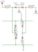
I'm currently playing with the attached idea. I stumbled upon it at THAT Corp. (in a design note and an AES paper) and later discovered it in some projects (i.e. a preamp by Uwe Beis).
The general idea is that the protection bridge is biased into not conducting under normal circumstances, as opposed to a diode that is directly attached to a supply line.
It should be noted that neither National (LME49990) nor TI (OPA1632) are telling us much about the internal clamping diodes at their ICs' input.
To be honest, I never actually heard a difference between diode circuits at amplifier inputs (nor did I ever try to).
Attachments
Last edited:
- Home
- Amplifiers
- Headphone Systems
- "The Wire" Ultra-High Performance Headphone Amplifier - PCB's