Hi Picovolt,
Yikes! That doesn't sound good!
I'm going to need a few good pictures of the amp itself, and if possible the setup it was in when this happened.
The amps themselves are very robust, and generally won't have problems once they're up and running. Even a short circuit on the output, or a surge on the input would be unlikely to cause issues.
The only thing that comes to mind is your grounding on the amps. Do you have a good ground connection to the input of the amp itself in addition to the two balanced inputs? I have seen one other person who didn't bother running ground to the amp (just +/- balanced), and a power transient caused the CM input voltage to exceed the op-amps limits, and damaged the LME49990.
For troubleshooting, remove the inputs and outputs and check all DC voltages. Power down and check for shorts between the inputs, outputs, and the rails.
Regards,
Owen
The only thing that comes to mind is your grounding on the amps. Do you have a good ground connection to the input of the amp itself in addition to the two balanced inputs? I have seen one other person who didn't bother running ground to the amp (just +/- balanced), and a power transient caused the CM input voltage to exceed the op-amps limits, and damaged the LME49990.
Regards,
Owen
Okay, guilty as charged. I haven't been running any grounds between my balanced gear. I have the dc offset at less than 1mv from my IV stage. Hum hasn't been an issue, and I've felt (mistakenly?) that the ground isolation was a good thing. I do have an earth ground on the chassis, but actually don't have a chassis yet on these, (just an acrylic plate).
The bal bal has been running for months wired just like that--perhaps I've just been lucky.
I do have the running amp to compare point voltages to. The only things I checked were the voltage at the PS caps (18.18/18.19) and then the speaker output, after the smoke. I'll take some pictures and post those. The amps sounded so good, certainly in the same family as the bal bal, but with more ease, and the images were at the correct height (off topic, but with the balbal, the soundstage was lower to the ground—very odd).
Hi Picovolt,
For some reason, the OPA1632 seems to be a little more robust in this regard than the LME49990.
I'm not saying that it's certain that's what happened, but it seems the most likely at this stage.
Even if the steady state offset of the source is only a few mV, transients on the power lines or the chassis of the source (ESD, or large power draw changes) can create momentary deltas of anywhere from a few volts, to a few hundred or thousand volts. This can either destroy or damage the LME49990.
The good news is you're probably alright to just swap out that op-amp, and a few dollars later you should be on your way. Hopefully the loudspeaker is also fine, and managed to tolerate the DC for as long as it was on. Fingers crossed!
Regards,
Owen
^^ Owen, thanks for the super speedy replies. I've got a few hectic days at work ahead of me, so other than ordering some chips, I won't be able to do much; I'll take some measurements first, in any case. From what you've said, it seems I should wire in the signal grounds though! Or, since the signal ground (from my DAC) is also not attached to the AC ground, is it better to use the ac ground in the amps input circuit?
Alan
Alan
So the ground planes from both your BalBal and LPUHP are each joined to their respective PSU's but not to each other and neither are connected to mains supply ground either?
Is there a voltage difference between the two ground planes? I once measured 5 Volts difference between unconnected ground planes within the same amplifier fed from different taps on the same transformer feeding separate supplies.
Owen, why did choose LME49990 for the input of the LPUHP instead of OPA1632? Prefered the sound? Measurements? 🙂
Hi Guys,
Indeed... grounding is tricky! Lot's of opinions in this area, and many vary wildly.
The critical aspect here is respecting the limitations of the CM or input voltage on the op-amps in the front end.
Assuming your cables aren't more than a few meters long, using the GND conductor and shield within the cable itself is probably sufficient to keep the amplifiers GND reference within a few volts of the GND reference for your source. The key is to avoid large loops caused by tying GND through both the AC mains and through the interconnect cables.
The problem comes when there is no common reference whatsoever. This can cause enormous potential differences in the various system references, and causes either serious issues, or in your case, damage.
I had very similar problems with the isolated SPDIF connection between my music server and my Behringer crossover. It would drop out every time my hot water heater kicked on, or if I had any static buildup and touched the PC itself. I was able to solve this by actually removing the isolation all together, an tying both grounds together. There was no increase in noise overall, and the sensitivity to transients disappeared.
As for the choice between the OPA1632 and the LME49990 parts, it was mostly one of architecture. I use the OPA for bridged architectures because it provides very good performance with both balanced and SE inputs, and differential outputs. It's less ideal when the outputs are single ended as they are with the LPHUP. With SE outputs, I prefer to use the LME49990 as it's my favorite standard op-amp both in terms of distortion, noise, and overall sound.
Cheers,
Owen
perfect !!!!
Owen, could you tell us more on this WPUHP amp ?
regards,
Richard
Hey Owen, I've just bought some speakers (KEF LS50's) and after building your HP amps, am keen to checkout your power amps for these bad boys 😀
Am I able to order your MPUHP amp boards (for stereo) with a power supply (or two if it's a dual mono arrangement)?
I'm happy with fully assembled or bare boards for amp, psu or both just let us know what's available - keen to get these as soon as I can to drive these speakers 😀
Thanks as usual Owen.
Blown 49990s
I finally had a chance to take some measurements, on both my good amp and the problem one. All of these measurements refer to U1, U2, and U3, and all measurements were taken with no load (open) and nothing connected to the input.
On the good amp, other than the supply pins, everything was ±0.1mv, except the outputs (pin 6) which were -2.3mv (U1) 0.3mv (U2) and -22.8mv (U3).
On the bad amp, for U1: pin2 (-8.31V) pin 3 (-7.72V) pin 6 (15.94V). For U2: pin 2 (-17.21V) pin 3 (-17.38V) pin 6 (-17.31V). And finally, for U3: pin 2 (-2.1V) pin 3 (-2.91V) and pin 6 (-16.71V).
So, Owen, as I was pretty sure—you were totally correct. I've already added the ground connection to XLR out in my DAC, and will wire it into the amps, so hopefully this will not happen again.
I am also very lucky—the speaker does not seem damaged, much to my relief. I "critically " listened to some mono feeds, and everything has stayed dead center.😀
A few questions:
1. I'm pretty certain that U1 and U2 are fried, and assume U3 is, but (since I truly don't understand the interactions of the op amps) U3 may be fine and is just reacting to the problems being handed down to it by U1 and U2. I have more coming in this week, so will plan on changing all three.
2. In the "good" amp, is the U3 output of -22.8mv still acceptable? I'd like to think that with no input, the output should be less than that. Should these also be replaced (ie, were they were damaged, but not totalled?)
3. In reading the TI data sheet, the max voltage is 18V. I'm about 1% over that on both sides of both amps—should I pull this back to 17.8V (eg.)—and if so, what value resistors should I use? Each amp has a 50VA transformer.
4. This is off topic. My case plan has an LED located right next to the transformer—almost touching it. This would mean having a twisted pair of leads going from the final cap on one of the power supply legs (with a drop down resistor) to almost wrap around the toroid on the way to the LED. This seems like it might not be a good idea, in terms of introducing noise back into the DC—but I'd like a more educated opinion on this.
As always, thanks in advance.🙂
Alan
Corrections to 49990 post above!
I should have worn my stronger reading glasses while listing the op amps. Everywhere I said U1 it should be U24, and U2 is really U22. U3, amazingly enough, stays as U3. I apologize if anyone read this question and thought it non-sensical. Now that I've pulled them off the board (with my double loupe on) I can easily read the correct numbers.
Alan
I finally had a chance to take some measurements, on both my good amp and the problem one. All of these measurements refer to U1, U2, and U3, and all measurements were taken with no load (open) and nothing connected to the input.
On the good amp, other than the supply pins, everything was ±0.1mv, except the outputs (pin 6) which were -2.3mv (U1) 0.3mv (U2) and -22.8mv (U3).
On the bad amp, for U1: pin2 (-8.31V) pin 3 (-7.72V) pin 6 (15.94V). For U2: pin 2 (-17.21V) pin 3 (-17.38V) pin 6 (-17.31V). And finally, for U3: pin 2 (-2.1V) pin 3 (-2.91V) and pin 6 (-16.71V).
So, Owen, as I was pretty sure—you were totally correct. I've already added the ground connection to XLR out in my DAC, and will wire it into the amps, so hopefully this will not happen again.
I am also very lucky—the speaker does not seem damaged, much to my relief. I "critically " listened to some mono feeds, and everything has stayed dead center.😀
A few questions:
1. I'm pretty certain that U1 and U2 are fried, and assume U3 is, but (since I truly don't understand the interactions of the op amps) U3 may be fine and is just reacting to the problems being handed down to it by U1 and U2. I have more coming in this week, so will plan on changing all three.
2. In the "good" amp, is the U3 output of -22.8mv still acceptable? I'd like to think that with no input, the output should be less than that. Should these also be replaced (ie, were they were damaged, but not totalled?)
3. In reading the TI data sheet, the max voltage is 18V. I'm about 1% over that on both sides of both amps—should I pull this back to 17.8V (eg.)—and if so, what value resistors should I use? Each amp has a 50VA transformer.
4. This is off topic. My case plan has an LED located right next to the transformer—almost touching it. This would mean having a twisted pair of leads going from the final cap on one of the power supply legs (with a drop down resistor) to almost wrap around the toroid on the way to the LED. This seems like it might not be a good idea, in terms of introducing noise back into the DC—but I'd like a more educated opinion on this.
As always, thanks in advance.🙂
Alan
Hi Alan,
I didn't even notice that you had those designations mixed up, I read your post and intuitively knew which positions in the instrumentation amp you were talking about. 🙂
Regarding your Q2, what shows at that point when you ground the input?
For Q4, I'd go without the LED personally.
Chris
I didn't even notice that you had those designations mixed up, I read your post and intuitively knew which positions in the instrumentation amp you were talking about. 🙂
Regarding your Q2, what shows at that point when you ground the input?
For Q4, I'd go without the LED personally.
Chris
A few questions:
1. I'm pretty certain that U1 and U2 are fried, and assume U3 is, but (since I truly don't understand the interactions of the op amps) U3 may be fine and is just reacting to the problems being handed down to it by U1 and U2. I have more coming in this week, so will plan on changing all three.
2. In the "good" amp, is the U3 output of -22.8mv still acceptable? I'd like to think that with no input, the output should be less than that. Should these also be replaced (ie, were they were damaged, but not totalled?)
3. In reading the TI data sheet, the max voltage is 18V. I'm about 1% over that on both sides of both amps—should I pull this back to 17.8V (eg.)—and if so, what value resistors should I use? Each amp has a 50VA transformer.
4. This is off topic. My case plan has an LED located right next to the transformer—almost touching it. This would mean having a twisted pair of leads going from the final cap on one of the power supply legs (with a drop down resistor) to almost wrap around the toroid on the way to the LED. This seems like it might not be a good idea, in terms of introducing noise back into the DC—but I'd like a more educated opinion on this.
Hi Alan,
Sorry for the late reply. I had a bunch of board orders come in (finally) so I had a lot of packing and testing to do over the past few days!
To answer your questions:
1. If the problem was one of excessive CM voltage, then there's a good chance U3 is fine as it would have been protected by the previous two op-amps. Best bet though is to replace them all just to be sure. Sometimes subtle damage to parts can manifest itself in odd ways, so it's better safe than sorry.
2. All that matters in this scenario is the actual DC offset at the loudspeaker output. That should be less than 10mV, and is nominally less than 2mV.
3. This will not cause any issues at all. The datasheet maximum voltage for those parts is +/-19VDC so as long as you're not creeping over that territory, you'll be fine. If you're under 18.5VDC I'd say just leave it. At 18.18V it's well within the realm of safety.
4. You won't have any problems with this. Any noise picked up on the leads (which will be minimal if you twist them) will be met by a very low impedance in the form of large caps and regulator outputs, and will tend not to couple onto the DC rails. In addition to this, you have very high PSRR on the op-amps themselves. If the LED was connected to the input of the amp I'd be worried, but that's not the case 🙂
I'm very glad to hear your speaker survived the ordeal! Also glad you've got the new parts coming to get these fixed.
If you want to be extra safe in the future, you can plunk a pair of TVS diodes across the top of R1 and R2 to protect the input of the op-amps. these will clamp the input to a value within the safe operating range of the op-amp, and should be effective against DC offsets or transients caused by ESD.
Pick a TVS that has a minimum clamping voltage a few volts over your input signal, and try to find one with the lowest capacitance possible.
Cheers,
Owen
While I'm in this thread I should ask a question of my own. 🙂
I was yesterday comparing the v1 and v2 LPUHP measurements. I noticed that the THD vs freq chart in post #1 in this thread increases (slightly) as freq increases for both 1W and 8W charts. The chart in post #149 of the board's FS thread, doesn't increase like that but also doesn't mention output power conditions that it was measured under (I'm assuming 1W here).
Is that a change in the measurement setup or a change in the performance with 4layers vs 3 layers and revisions to PSU? (These seem unlikely)
Cheers,
Chris
Hi Chris,
The delta you're seeing there mostly has to do with whether the input low pass filter on the AP is enabled.
The first two THD measurements of the V1 unit are done without any input low pass filter on the AP, so the measurement is being done from DC up to 80kHz which is where the AP's built in AA filter is. As a result all the harmonics of higher frequencies are being captured and added to the THD number, even though they are well outside the audible band. For example, at 10kHz you would capture everything up to the 7th harmonic, which would be at 70kHz.
The measurement for the V2 was done with the LPF turned on at 24kHz. The result of this is that distortion plummets to nothing after about 12kHz because the harmonics of frequencies above 12kHz are being fully attenuated. The other side effect is that higher order harmonics of frequencies below 12kHz are also being attenuated, so at 1kHz, you're capturing every harmonic up to the 23rd, but at 8kHz, you're starting to attenuate the 3rd harmonic and essentially eliminating everything above that. The end result is that distortion doesn't rise like it does if you have the LPF turned off.
I have heard arguments in both directions on this, but industry standard is generally to measure with an LPF turned on. The argument for that is the obvious one: if you can't hear above 20kHz or so (much lower for most of us!) then why be concerned about a harmonic that falls above 20kHz? If you look at it this way, then all distortion measurements above 8kHz are meaningless to pretty much everyone over the age of 30 as you won't be able to hear the second harmonic, regardless of how high it is.
I have also heard other arguments that those HF harmonics can manifest themselves at lower frequencies that are audible, or that when those higher order harmonics are sent through to a transducer, they can cause IM distortion which will fall into the audible band. I personally haven't experienced this, but there could certainly be some validity to the latter argument.
I usually try to include both measurements to be fair, and if you look at the third THD measurement for the V1, you'll see the same measurement as the first two but with the LPF enabled. I didn't include this much detail when measuring the V2 as it was mostly a validation exercise.
My biggest problem with the whole thing is that when distortion is extremely low, as it is with the LPUHP, the AP starts to confuse noise with distortion, and just THD measurements become difficult and a little inconsistent. If you look at the third measurement of the V1 with the LPF enabled, you'll notice that THD is lower across the entire band. This is because HF noise is being eliminated by the LPF, and is no longer artificially elevating the overall THD measurements. This measurement is most representative of the actual distortion components, but it's not accurate for true distortion above about 8kHz. For that, you'd need to combine the trend of the graphs with the LPF disabled with the absolute level of the graph with the LPF enabled.
Hope all this makes sense! Maybe if I can get my hands on a APx555 I could get slightly better measurements 🙂
Cheers,
Owen
Ah, yep that makes sense.
I was looking at the Modulus86 measurements the other day and comparing them also. The spiel on the page suggests that flat THD vs freq is helping the subjective impresion of the amplifier. I wonder if he had the LPF on? I'd have to go looking in those threads I guess. I have no time/interest in building that amp at this stage but was just something that got my interest so I went and re-looked at the measurements from LPUHP and LME49830 amps and had a quiet (smug) smile to myself.
Cheers,
Chris
Up and running (again)
Thanks for the replies, Hochopeper and Owen. (OOOOH, new boards!)
I replaced all three op amps between posts, and have the blown amp running again. It measured fine, so I hooked up another test speaker (sister to the now defunct one) and got dead silence. Luckily, before getting too depressed, I realized that I needed to plug the amp back in—no AC, no noise. It’s embarrassing how often this happens.
Anyway, shorting the input takes care of the small current I measured on the “working” amp before—thanks. And, after an evening spent listening, I certainly can’t tell if there’s a difference between having the grounds now connected—other than feeing a bit safer. I think I’ll wait before adding in TVS diodes; if I lose any more op amps here, I’ll order some with the replacements and do just that.
Lately I’ve been making my front panels from wood, and using 1/16th inch plex rod in front of the LED, so that it‘s a small dot; I like having some indication that power is active. Before getting your responses, I decided to try making a long curved light pipe with the 1/6th inch rod—if this works, it means I can keep the wiring away from the transformer. I understand it’s not needed (thanks for the explanation that even I could understand)—but it’s a nice small challenge.
So far, the only amps I’ve used on the (new) higher efficiency speakers have been Wires (BAL BAL and now these). So, I’m pressed to tell how much of what I’m hearing is from the amps or speakers. There is definitely more than just a volume difference between the BAL BAL and the LPUHP amps—both certainly are in the same family; possibly its the op amps‘ sound that is making the difference. I’m having a hard time accepting the quality and amount of bass I’m getting from a pair of 10cm drivers...😉
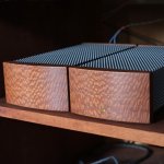
Photos
I had a slow few days at work so I was able to machine the case parts faster than I was expecting to. Fronts and back panels are milled from lacewood. The basic chassis is laser cut black acrylic. The light pipe worked great for the LED. I keep kidding myself that I will eventually get these parts (similar construction on my other projects lately) waterjet cut from aluminum and anodized (less necessary on a small box like these). Same with the perf aluminum—currently its just lacquer rather than anodized.
Pamona makes tellurium copper binding posts; I had never used them before, and while they're not as classy looking as many others, I've come to believe in the "less metal mass" for connectors. I've also been using Schurter AC inputs for a while now and really like their build quality.
The amps have about 75 hours on them now—I'm really please with the sound.
Attachments


Wow... picovolt, those are stunning!
I love the curved wood front panels and the Dynaco style cage. Super clean, very modern, but still a little retro.
Excellent internal layout as well. Everything looks pretty much spot on.
You've got a nack for industrial design!
Also agreed on the Schurter stuff. I plan to use them for my production amps. I just wish they didn't cost an arm and a leg!
Congrats on the new amps!
Cheers,
Owen
Picovolt, very nice work!
😎
I've been eyeing those pomona binding posts too, they look like just the right amount of overkill for my taste, I use speakon connectors for speakers mostly so haven't really found an excuse yet.
😎
I've been eyeing those pomona binding posts too, they look like just the right amount of overkill for my taste, I use speakon connectors for speakers mostly so haven't really found an excuse yet.
Thanks guys—I have to admit that I like to "personalize" my equipment, and usually spend more time on the housings than the rest of the construction, (except maybe parts sourcing on some projects).
It's funny you mention Speakon connectors, Hochopeper. I had asked about them in the speaker threads and didn't get answers about their sonic quality. I've used them in "pro audio" speakers and amps and know them to be totally reliable (and way better than the phone plugs that they are generally replacing). Since I rarely need to change speakers, etc. I'm quite happy with the "smashed wire" connection I get with the Pomona posts. The other option I had considered was just an old style screw barrier strip.
I keep looking at the nude BalBal board and am thinking of designing a housing that is tiered, with it on top, like the bride and groom on a wedding cake.
perfect !!!!
Owen, could you tell us more on this WPUHP amp ?
regards,
Richard
Hi Richard:
Details and measurements for the MPHUP (Medium Power Ultra High Performance) just posted in the main PCB forum starting with this post:
http://www.diyaudio.com/forums/vend...-here-bal-bal-se-se-lpuhp-69.html#post4282575
Details for the HPUHP (High Power Ultra High Performance) will be posted tonight or tomorrow. It's a mono 100W into 8 ohm (bridged), or a stereo 50W into 4 ohm (SE) amplifier.
Cheers,
Owen
- Home
- Amplifiers
- Solid State
- The Wire - Low Power Ultra High Perfromance (LPUHP) 16W Power Amplifier