Hi! Sorry for the question...... How do you know when your boards are shipped? Am I supposed to get an email?
Hi! Sorry for the question...... How do you know when your boards are shipped? Am I supposed to get an email?
Yes, I will send an email with the tracking number.
So my package is standing too, form march 30 nothing has changed in tracking status.🙁
SDA is very slow now...
SDA is very slow now...
Same case with me.It will probably come in the next few days.So my package is standing too, form march 30 nothing has changed in tracking status.🙁
SDA is very slow now...
Where have people purchased the below as Mouser have no estimated delivery date?
Anyone found an equivalent?
1812CS-332XGLC
1812 3.3uH Unshld 2%
Coilcraft Fixed Inductors
Anyone found an equivalent?
1812CS-332XGLC
1812 3.3uH Unshld 2%
Coilcraft Fixed Inductors
@Terry Demol: Just for clarification ... Are you talking about the output decoupling capacitor (>=4.7uF, less than 50 mohms & 2nH inductance according to data sheet) or are you thinking about the capacitor that may decouple the voltage setting resistor (e.g. up to 22uF). There isn't really any "ref" capacitor ;-)
Cheers,
Jesper
Hi Jesper,
Yes the set pin. It's a high impedance reference point.
TCD
The set pin capacitor could modulate the regulator output if it is a piezoelectric type (class II ceramic) and there is PCB vibration.
Hogwash.
There is no need to bolt the regulator to the engine of a helicopter.
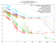
This board was done from A-Z on a rainy Sunday. Circuit is directly
from the data sheet, measurement is limited by the preamp below 100 Hz.
Completely unshielded, open on the lab table, next to the computer screen,
under the switched LED microscope ring light and in the front of a 2*4
square meter array of 19" scopes, generators, spectrum analyzers etc,
each with a switching power supply of their own.
Fed by a R&S NGT20 via 1.5m banana cable.
X7R ceramic capacitors and still 2 nV/rtHz noise density, just as promised.
0 dB line is 1 nV/rt Hz, 6 dB more is 2 nV.
more on < spectrum_lt3042_DH44 | Noise spectrum of the LT3042+ D44VH10… | Flickr >
Gerhard
The noise at 10Hz looks similar to an LM317. At 1Hz it's 3000 nV/rt Hz. But as you say it's limited by preamps noise so the plot is not of much use for
LF noise which is where I saw MLCC manifest when used on set pin.
I did not do extensive measurements, just observed it - it was a job that had
to go out. I think I have one of these 3045 pcbs left so if I have time I'll look
further into it.
TCD
Where have people purchased the below as Mouser have no estimated delivery date?
Anyone found an equivalent?
1812CS-332XGLC
1812 3.3uH Unshld 2%
Coilcraft Fixed Inductors
https://ie.farnell.com/coilcraft/18...-3uh-2-145mhz-rf-smd/dp/2286999?st=1812cs-332
Where have people purchased the below as Mouser have no estimated delivery date?
Anyone found an equivalent?
1812CS-332XGLC
1812 3.3uH Unshld 2%
Coilcraft Fixed Inductors
It's difficult to find a replacement, it's a ceramic core inductor with high self resonant frequency and low tolerance (2%).
The only chance is using the 5% tolerance one 1812CS-332XJLC but the oscillator may not start.
In that case you should adjust C27-C28 by a few pF to realign the resonance of the tank (L4-C27-C28-C38).
Is this one OK as Lasercut suggested?
https://ie.farnell.com/coilcraft/181...?st=1812cs-332
UK site and looks the same spec....
https://uk.farnell.com/coilcraft/18...-3uh-2-145mhz-rf-smd/dp/2286999?st=1812cs-332
please confirm its Ok - thanks!
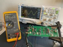
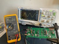
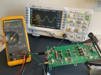
Power supply effect
Hi,
I have noticed that lower supply voltage distorts the sine wave.
See attached pictures; on 12v the bottom of the sine is distorted, on 18v it looks much better.
It is specified to be powered from 12-18v.
I do not know if this will impact the clock signal after squarer.
I also have problems getting this clock to lock on the fifopi. On the scope it looks fine as far as I can judge but I get no music. Power supply is from 5 LiFePo4 batteries=16,5v.
What can be the problem?
My other 3 clocks are working.
Attachments
Last edited:
Good feedback. Maybe I'll turn the power up closer to 18v. May not affect when it triggers the squarer, but better to be perfect.
The noise at 10Hz looks similar to an LM317. At 1Hz it's 3000 nV/rt Hz. But as you say it's limited by preamps noise so the plot is not of much use for
LF noise which is where I saw MLCC manifest when used on set pin.
I did not do extensive measurements, just observed it - it was a job that had
to go out. I think I have one of these 3045 pcbs left so if I have time I'll look
further into it.
TCD
There is quite a difference between a LT304[25] and an LM317.
And when I write that the preamplifier is the culprit below 100 Hz (in fact, some 100 Hz)
then I mean it.
Scott saw it on the spot in a different thread that the preamp has
no 1/f noise but 1/f**3 ( 30 dB/decade). That's for the size of the input capacitor
that was way to small @ 100u foil - that could not short the bias noise through the
low-Z DUT. A 4700 uF wet tantalum was about right but introduced other problems.
But I have now a new pre amplifier that does not have 20 parallel bipolar
low noise op amps but 16 JFETs where 10u is large enough.
Repeating the measurements with the new preamp will take some time.
My soldering iron, the WIMAs and the relays must have a special love/hate relationship.
Attachments
Last edited:
Hi,
I have noticed that lower supply voltage distorts the sine wave.
See attached pictures; on 12v the bottom of the sine is distorted, on 18v it looks much better.
It is specified to be powered from 12-18v.
I do not know if this will impact the clock signal after squarer.
I also have problems getting this clock to lock on the fifopi. On the scope it looks fine as far as I can judge but I get no music. Power supply is from 5 LiFePo4 batteries=16,5v.
What can be the problem?
My other 3 clocks are working.
We have tested the oscillator at 12V and it did work without any problem, however we suggest 16-18Vdc to get a little better noise floor.
The scope plot is strange because clipping cannot happen since the output is AC coupled.
It looks like a impedance matching issue, I'm sure the sinewave is not distorted.
About the FifoPi locking, at what frequency the oscillator is running?
You can measure the frequency with your Rigol scope.
- Home
- Group Buys
- The Well Tempered Master Clock - Group buy