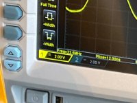
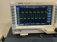
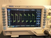
According to the scope it is at the designed frequency, the scope rounds it off to 22,5mhz, see picture. But it shifts a bit between 22,4-22,7mhz. I do not know if it is the accuracy of the scope, test leads or the way I have connected the clock to the scope.
You are right about the impedance. A test with 47ohm load looks a lot better!
Sorry for the mistake😱
You are right about the impedance. A test with 47ohm load looks a lot better!
Sorry for the mistake😱
Attachments
Last edited:
So the frequency is correct, strange that the FifoPi does not lock.
Can you put the probe at the output of the sine to square converter?
Can you put the probe at the output of the sine to square converter?
D
Deleted member 537459
Hi,
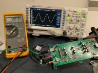
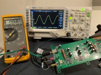
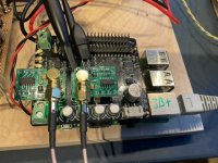
I have noticed that lower supply voltage distorts the sine wave.
See attached pictures; on 12v the bottom of the sine is distorted, on 18v it looks much better.
It is specified to be powered from 12-18v.
I do not know if this will impact the clock signal after squarer.
I also have problems getting this clock to lock on the fifopi. On the scope it looks fine as far as I can judge but I get no music. Power supply is from 5 LiFePo4 batteries=16,5v.
What can be the problem?
My other 3 clocks are working.
Are you sure is correct crystal? The board is drixo, I se in the picture the crystal is tiny.
Are you sure is correct crystal? The board is drixo, I se in the picture the crystal is tiny.
Size doesn't matter 🙂
5-6mhz has different form factor than the 22.xxxx/25.xxxx
According to the scope it is at the designed frequency, the scope rounds it off to 22,5mhz, see picture. But it shifts a bit between 22,4-22,7mhz. I do not know if it is the accuracy of the scope, test leads or the way I have connected the clock to the scope.
You are right about the impedance. A test with 47ohm load looks a lot better!
Sorry for the mistake😱
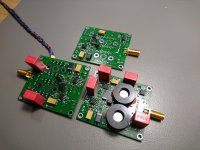
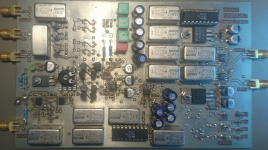
why you left unsoldered the two caps near the voltage reference ? (aka C43-C45)
why you left unsoldered the two caps near the voltage reference ? (aka C43-C45)
Thanks ... I had not seen.
These capacitors are mandatory, without them the voltage reference oscillates.
But I have now a new pre amplifier that does not have 20 parallel bipolar low noise op amps but 16 JFETs
OMG, you arrived at this solution
 . And how’s the stability, does it sing ?
OMG, you arrived at this solution. And how’s the stability, does it sing?
P.S. Took a second look at your board, and I spotted those little pesky gate inductors
. That must be it .No, it does not sing; unlike ~HPM6.1 or what it was called it has no negative
input impedance at 100 KHz because of the delayed feedback.
The 4 parallel gate/drain lines would form an efficient resonator
at 650 MHz, and the 16 CPH3910 would be more than happy to put it
to use.
If the ferrite beads had an stability effect at 100 KHz, they would also
have a noise effect at 100 KHz.
I had FET amplifiers long before, {pic1}, Interfet IF3602 or a herd of BF862
and the Wenzel design ( from his phase noise measurement machine, pic2,
partly populated ) even 10 years earlier.
They all share the misfeature of not being unconditionally stable.
Gerhard
Attachments
Last edited:
You must be joking, “delayed feedback” 😀.
And you know that, reactances have no Johnson noise, while the input current of JFETs is virtually nil, so no noise current drop.
Glad you finally arrived to the solution I built 10 years ago, too bad you wasted time on all kind of other hopeless attempts. Your next step is to go to 64 JFETs in parallel, you’ll get at 0.15nV/rtHz like myself.
Don’t worry, I’m not asking for royalties, after all this idea was developed in the ‘60s.
And you know that, reactances have no Johnson noise, while the input current of JFETs is virtually nil, so no noise current drop.
Glad you finally arrived to the solution I built 10 years ago, too bad you wasted time on all kind of other hopeless attempts. Your next step is to go to 64 JFETs in parallel, you’ll get at 0.15nV/rtHz like myself.
Don’t worry, I’m not asking for royalties, after all this idea was developed in the ‘60s
.
Last edited:
Thanks ... I had not seen.
These capacitors are mandatory, without them the voltage reference oscillates.
Yes, thanks for your help! I have overlooked this in the process of building 6 of these modules, after soldering so many components I missed these. How stuped of me 🙁
I soldered the caps and now it is working!
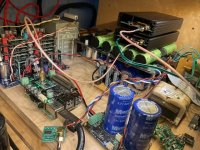
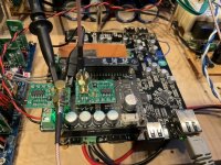
Now another problem has arisen. The fifopi does not lock onto the clock when two of them are connected. I have the 22 and 24mhz clocks connected. I can only use one of them connected.
I sent Ian a message of this problem but he has no solution.
One note he made was that the XO output logic levels might be too low.
On the picture you can see the setup on my dddac with 22-24mhz clocks.
Attachments
re two clocks connected to FIFOPi
Supersurfer, am I correct in my recollection that two clocks without the sensing function can only be used with FIFOPi Q3? I have one of the earlier versions and assumed I could only ever connect one WTMC. Is that correct?
Supersurfer, am I correct in my recollection that two clocks without the sensing function can only be used with FIFOPi Q3? I have one of the earlier versions and assumed I could only ever connect one WTMC. Is that correct?
Hi Walter,
I have been using two previous clocks from Andrea on the fifopi q1 without any problems. I do not see why these would not function in the same manner.
I have been using two previous clocks from Andrea on the fifopi q1 without any problems. I do not see why these would not function in the same manner.
Yes, thanks for your help! I have overlooked this in the process of building 6 of these modules, after soldering so many components I missed these. How stuped of me 🙁
I soldered the caps and now it is working!
Now another problem has arisen. The fifopi does not lock onto the clock when two of them are connected. I have the 22 and 24mhz clocks connected. I can only use one of them connected.
I sent Ian a message of this problem but he has no solution.
One note he made was that the XO output logic levels might be too low.
On the picture you can see the setup on my dddac with 22-24mhz clocks.
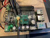
Please, put your probe at the output of the two sine to square converter when both are connected to see the output level.
The output should be a square wave from ground to around Vcc of the squarer.
I did some measurements and this shows that the q1 fifopi has issues with 2 clocks.
First 2 pictures; two clocks
Last 2 pictures; one clock
First 2 pictures; two clocks
Last 2 pictures; one clock
Attachments

Before FIFO_Pi 3, the old FIFO_Pi design used the disable pin on the clocks as needed to turn one clock off, and turn the other clock on. Since Andrea's squarers don't have a disable pin, the old FIFO_Pi clock selection system won't work with two of them. With FIFO_Pi 3, it isn't required to use the clock disable pin, there is some other means of gating which clock is enabled and which one is disabled. That means two squarers can be used.
Last edited:
Before FIFO_Pi 3, the old FIFO_Pi design used the disable pin on the clocks as needed to turn one clock off, and turn the other clock on. Since Andrea's squarers don't have a disable pin, the old FIFO_Pi clock selection system won't work with two of them. With FIFO_Pi 3, it isn't required to use the clock disable pin, there is some other means of gating which clock is enabled and which one is disabled. That means two squarers can be used.
+1
- Home
- Group Buys
- The Well Tempered Master Clock - Group buy