What regards the close-in phase noise contribution of the LTC6957, it had been measured here, and I hope it's ok if I repost here together with the link?
Phase Noise and other Measurements with a Timepod - KO4BB
Could it be called non-existent below 100 Hz, for our purposes?
Phase Noise and other Measurements with a Timepod - KO4BB
Could it be called non-existent below 100 Hz, for our purposes?
Attachments
This LTC6957 looks interesting. I see that Andrea is designing some LVDS products. How about putting the LTC6957 into the oscillator boxes and send differential LVDS clock signals to the DAC instead of single-ended signals?
Last edited:
While some of the LVDS clock distribution chips, clock dividers, and multipliers look very interesting in terms of specified phase noise, it remains the case that most audio clocks and most dac chips work with LVCMOS signals. It means that phase noise of chips for converting from one signal format to the other also should be considered in weighing the pros and cons of such a clock distribution system. So far I haven't seen any discussion of that issue, did I miss it somewhere?
well, just my crazy acting up on a less smokey Friday morning. But if one is already sending CLK via LVDS....
See pictures
https://www.diyaudio.com/forums/dig...uffer-slaved-i2s-reclocker-2.html#post6340035
See pictures
https://www.diyaudio.com/forums/dig...uffer-slaved-i2s-reclocker-2.html#post6340035
It is interesting to compare the different versions of the LTC6957. IIRC, the
LVDS version is the worst. That's for everything else being equal. The chips
are probably just bonding options of the same design.
The problem with LVDS seems to be the "low voltage difference" in its name.
LVDS version is the worst. That's for everything else being equal. The chips
are probably just bonding options of the same design.
The problem with LVDS seems to be the "low voltage difference" in its name.
We chose LVPECL for that reason for our clock distribution scheme on our multi channel DAC board. It simply uses higher signal voltage/power and should have better immunity to emi and have higher snr.
Of course you have to convert it to a single ended signal right at the DAC chip again but IMHO the benefits of differential clock distribution over sufficient distances (Max 15-20cm) will outweigh the added complexity and the added phase noise of the conversions. The plot that Andrea posted of the 74ac04 based converter clearly show that it's contribution to overall phase noise is almost negligible with the excellent oscillator still being the main contributor.
One more thing to note, differential signals have the added benefit of not introducing return currents in the ground plane, a widely underestimated contributor to "digital noise" in analog circuits.
Exactly. Differential signals contribute less to ground noise.
The thing with the ltc part is that for the differential cmos version the timing is not exact. It is specified within a few picoseconds or so for lvds, ecl and the in phase cmos. Sadly not for the differential cmos. Iirc it could mean you need a centimeter or more to adjust, and differs from ic to ic. Undoable.
Nonetheless, I used it and does work well. It also has a high load capability, but for long cables I'd take the ecl, also because it has 2 pairs of output signals.
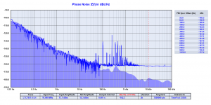
What regards the close-in phase noise contribution of the LTC6957, it had been measured here, and I hope it's ok if I repost here together with the link?
Phase Noise and other Measurements with a Timepod - KO4BB
Could it be called non-existent below 100 Hz, for our purposes?
It's very curious that now you trust the reliability of the Timepod measurements. It looks like the gear was allergic only to the ultimate devices.
BTW, even the 74AC04 sine to square converter seems to be non-existent below 100 Hz, only a little higher noise floor, so sorry but I have no time to design one more squarer.
As I said we are already devoloping another sine to square wave converter for the top version of our system, but it's could be called "RF style" since it uses discrete devices only.
BTW, even the 74AC04 sine to square converter seems to be non-existent below 100 Hz, only a little higher noise floor, so sorry but I have no time to design one more squarer.
I see I had earned Your simpathy.. 🙂 I hope it might change, still..
But look, there is a good 50; 30dB difference at 1Hz, 10Hz, between these two tests, so either the logic gate does something extra there or does have no contribution..
We do not know, at least from that graph.
The LTC6957 will not increase the floor even with Your best 5MHz Driscoll oscillator. According to Bruce's measurement, at least..
Attachments

Last edited:
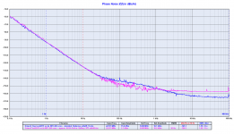
I believe you are wrong, the simple gate sine to square converter does not add anything to the close in phase noise of the oscillator as you can see in the attached plot, 1/F and 1/f3 noise are superimposable.
As I said it adds noise floor and it's obvious since the gate operates as a non linear amplifier.
Moreover when a gate swithes there is a time when the channel is open, this time depends on the gate speed.
In this time the noise could cross the gate and show up at the output.
This could explain the noise floor while the close in noise is kept at low level, the same of the oscillator.
Slow edges do not have the time to cross the channel because the channel closes before they can cross it, while faster edges might cross it.
This could happen inside the 74AC04.
Thta's the reason why we are developing one more converter to achieve the better performance as possible along all the noise spectrum.
Attachments

Last edited:
Your graph is much more convincing than the previous one, thanks!
I have difficulties to follow your explanation, though..
Your graph is showing PM, slight variations in the switching time, and that decision is made in function of the input signal with respect to a threshold. The input signal sees the cmos gate input impedance, which is a high, ~constant value?
It is the impedance in the output stage which can have a dynamic impedance variation, while the output signal is 'slewing'..
I don't see how that could influence the decision time for switching. If not dragging the power supplies, and the gate has 6dB PSRR.. So a moving power supply does get translated to phasemodulation.. And the cmos gate input referred noise as well..
Ciao, George
The output impedance of the oscillator is 50 ohm and it's terminated to the 50 ohm input of the sine to square converter.
It's not a problem of impedance fluctuaction, at one side the noise floor comes from the CMOS gate that works in saturation generating a lot of harmonics that can modulate the phase noise with reflections to the input. From the other side the CMOS gate has poor PSSR so any noise coming from the power supply are reflected to the output.
When the channel of the CMOS is open all the crap flows in both directions and modulates the phase noise.
However if you liked my sympathy I could say that I have never named this little device the ultimate way to convert sine wave to square, it's simply a little board designed to fit the ultimate FIFO buffer.
Jokes aside it does its job properly since it does not add close in noise, allowing you to take advantage of the most performer oscillators with a little size board.
And lastly it's inexpensive.
Last edited:
Just a quick thought WRT various logic familes and jitter / phase noise.
It might be worth measuring phase noise of a Potato Semi inverter or flip flop
to see if their claims of very low jitter are BS or not. I don't know of anyone
that has actually measured one of these chips. All I can say is they are very
fast.
TCD
It might be worth measuring phase noise of a Potato Semi inverter or flip flop
to see if their claims of very low jitter are BS or not. I don't know of anyone
that has actually measured one of these chips. All I can say is they are very
fast.
TCD
I have never seen Potato offered anywhere but on Ebay. They don't
seem to play a role in the professional market.
And they play games with specs. I. e. specifying inverter delay
with less load than their own input, they could not drive themselves.
IIRC, it was about half a pF load, that would be just enough for my
Agilent 2.5GHz active probes.
Then I might be better off to use no gate at all.
Gerhard
Last edited:
I have reasons to believe Gerhard is right.
Their specs are, dubious - at best.
Their ebay account is inactive, & their US company address seems to be a residential house.
Even the name "Potato" should be enough warning for the diy enthusiast to approach with care.
Their specs are, dubious - at best.
Their ebay account is inactive, & their US company address seems to be a residential house.
Even the name "Potato" should be enough warning for the diy enthusiast to approach with care.
Last edited:
Why is the 25MHz frequence so difficult/impossible to get as a SC-cut crystal, so the Best solution TWTMC-DRIXO can be used? 6.25, 12.5, 50, 100MHz is also impossible?
There is no problem to get SC-cut crystal at 25 MHz and also there is no problem to get the TWTMC-DRIXO working at 25 MHz.
No problem at all to get SC-Cut crystals at 6 or 6.25 MHz.
The upper limit for the TWTMC-DRIXO we have imposed is around 30 MHz, so all the specified options are available:
- 24 MHz with TWTMC-DRIXO + crystal at 24 MHz
- 25 MHz with TWTMC-DRIXO + crystal at 25 MHz
- 6 to 24 MHz with TWTMC-DRIXO + crystal at 6 MHz + 2 doublers
- 6.25 to 25 MHz with TWTMC-DRIXO + crystal at 6.25 MHz + 2 doublers
- 25 to 100 MHz with TWTMC-DRIXO + crystal at 25 MHz + 2 doublers
The only issue is the MOQ for the crystals, so I recommend all of you to choose one solution that allows to meet the MOQ.
Hi Andrea. Are you only waiting for MOQ to be reached, or do you have a specific date range you are aiming to make the order?
We are testing and tuning the last boards (Frequency doublers to 45/49 and to 90/98 MHz, Differential oscillators from 11 up to 24 MHz, New Pierce oscillators from 11 to 98 MHz) and we are trying to develop the Pierce combo oscillator.
Moreover we have to test the last boards and the firmware of the LiFePo4 battery power supply.
As soon as the above work is done I will publish all the BOMs and the price list to collect your orders.
Those who have already made their choice regardless of the price could fix definitely their option on the GB thread.
Instead who waits for the last mesurements and for the final price list should wait until the end of the tests.
To place the order I need to know exactly the quantity of each crystal type (cuts and frequencies) because I'll only order what meets the MOQ.
- Status
- Not open for further replies.
- Home
- Source & Line
- Digital Line Level
- The Well Tempered Master Clock - Building a low phase noise/jitter crystal oscillator