Thanks Andrea, for sharing and all the good work,
Does Laptech provide an individual measurement for each crystal ? Or are they especially choosed in a range they product (concinstency ?). Will you compare it with a part they sent you already ?
Next step I have to source a USB to I2S or a TCP/IP to I2S streamers which can be slaved...
Wave I/O : ok (thanks guys: Andrea for the question to Lucian and answer for tis last above 🙂)
Any else ?
Thanks Andrea, for sharing and all the good work,
Does Laptech provide an individual measurement for each crystal ? Or are they especially choosed in a range they product (concinstency ?). Will you compare it with a part they sent you already ?
Next step I have to source a USB to I2S or a TCP/IP to I2S streamers which can be slaved...
Wave I/O : ok (thanks guys: Andrea for the question to Lucian and answer for tis last above 🙂)
Any else ?
I think they will test each crystal to check that the minimum specs are reached, but I don't know if they will send me these measurements. I will ask the question directly to Laptech.
About a slaved USB to I2S board, next days I will meet the Amanero's technical staff, so I will ask them about this option.
I see many people use the Raspberry Pi, but I don't know if it could be used as a slaved source.
Another option could be the BBB from Twisted Pear
http://www.diyaudio.com/forums/twisted-pear/250583-building-open-embedded-audio-applicance-117.html
but it's not clear to me how it could be connected to external clock.
Yes not sure the Amanero provides vias for that if the crystals are removed like the WaveI/O does !
That's also my understanding BBB could be slaved ! But really don't know how is the layout to source the I2S signals... Wlowes member uses a BBB on the Distinction-1541 pcb GB thread. But I believe he doesn't use an external clock with it.
regards
Eldam
That's also my understanding BBB could be slaved ! But really don't know how is the layout to source the I2S signals... Wlowes member uses a BBB on the Distinction-1541 pcb GB thread. But I believe he doesn't use an external clock with it.
regards
Eldam
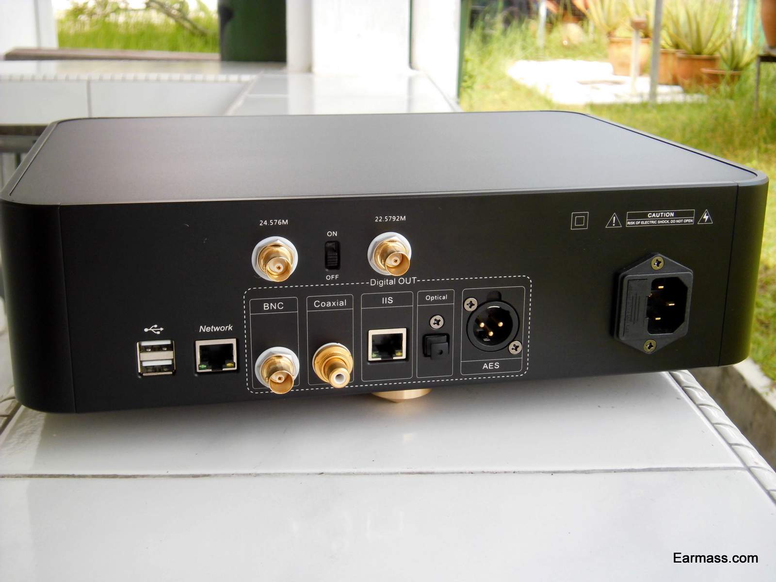
I am using the SoundAware D100 Pro Deluxe Network player which can accept master clock in. The master clock in requires a 3.3V at 75ohm load similar to typical coaxial inputs. Is there a way to get TWTMC to work with this network player, assuming I install the TWTMC pcb inside the player going to the same connections as the 22 and 24MHz master clock inputs.
Thanks.
Thanks.
I am using the SoundAware D100 Pro Deluxe Network player which can accept master clock in. The master clock in requires a 3.3V at 75ohm load similar to typical coaxial inputs. Is there a way to get TWTMC to work with this network player, assuming I install the TWTMC pcb inside the player going to the same connections as the 22 and 24MHz master clock inputs.
Thanks.
Are you sure these are 75 ohm connectors? Usually, line clock is 50 ohm, even using BNC connector.
If these are 75 ohm BNC you could use an impedance adapter (50 to 75 ohm, SMA to BNC).
If you would install the TWTMCs inside the player (if you can find enough space for 2 XO and daughter board), you could replace the 33R output resistor of the 2 XOs with a 50/56R. In this case, you could solder RF cables inside the player (if there are cables) directly to the XO outputs.
Thanks Adrea.
I believe they are 75 ohms if connect externally. Internally right at the clock input, it looks like it's a 50ohm adapter (see link below). I need to open up casing to confirm. There's ample space...so looks like this is highly do-able. Can't wait for the TWTMC to be here. 🙂
http://www.soundaware.net/bbs/data/attachment/forum/201305/29/102407fwc9s4gf9gc4tcp0.jpg
Are you sure these are 75 ohm connectors? Usually, line clock is 50 ohm, even using BNC connector.
If these are 75 ohm BNC you could use an impedance adapter (50 to 75 ohm, SMA to BNC).
If you would install the TWTMCs inside the player (if you can find enough space for 2 XO and daughter board), you could replace the 33R output resistor of the 2 XOs with a 50/56R. In this case, you could solder RF cables inside the player (if there are cables) directly to the XO outputs.
Any jitter measurement of the device and how they measure it ! I'm not sure there is any interest with longer wire to feed a MCLK or to put signal clock from it ! longer cable= bad gadget= marketing gadget & jitter and EMI coupling ! That's what I am tempted to believe !
I could live with the 50 pS of the SB Duet because the low price (have it already 🙂 )
Modding an off shelves expensive (?) device is not what I plane or I will go to a SD card reader like Andrea plans or CFT fellow did in a GB !
the bigger BBB (with tcpip) is 90 euros ! (But really don't know the quality of the layout with the I2S output ! )...
How can we measure the impedance of a plug ?
Last edited:
It's obvious from looking at the BNCs in the picture that they are the 75 Ohm version. Whether the circuitry behind the panel is 75 Ohms is another question.
You can measure the impedance of the connector and the cable and the termination with a TDR. Its not a simple thing to do with enough resolution to see the effects of the different sections of the link. And you learn really quickly that with the frequency range and rise times used for digital audio these links are all too short to have major effects.
My experience is that you will get more jitter from ground loops, crosstalk and external interference than from longer cables.
The best way to test for jitter is in the analog output. That will be the composite of all the jitter sources. That's also where the hum, crosstalk and data dependent jitter shows up. It rarely if ever shows at the clock itself.
Comparing clocks.
I am currently using the potato PO3B3306A bus switch device to switch clock sources on my DAC.
Much easier to use than relays.
Twistedpear use similar (analoge switch) devices on the BuffaloIIIse to switch the input signals.
Do they introduce jitter ? (the data sheet suggests not).
Anyone who can test ?
Regards,
Dean.
Hi Andrea, I´ve just added myself to the list.
Where should we email the order form ?
best regards
Pepe
Second batch
- Miklos: 1 x 16.9344 MHz
- Marlowe: 3 x 16.9344Mhz + 3 x 25MHz
- carz 1x 27MHz
- 1audio : 1X6.1440MHz
- mravinsky : 1 x 16.9344Mhz
- triodehunter: 1x 25.0000 MHz
- noizas : 2 x 16.9344 MHz
- randytsuch: 2x 25.0000 MHz
- lindamar: 1 x 45.1584 MHz + 1 x 49.152 MHz + 1 x 90.3168 MHz + 1 x 98.304 MHz + 4 x PCB + 2 x daughter board + 2 x adapter board
Last edited:
Andrea,
Maybe the USB OEM board made by Joro could be a good candidate for me not to explose the cost with a SD card reader ! It has no isolator as it is made to be just an input USB module for more complex design than a standalone pcb like the Wave I/O is and where all is embeded. But it has relativly close vias with multiple Gnd vias near its chip to hack the I2S signal (as and this is the goal: an input MCLK via with a non too far gnd via !).
OEM board - I2S over USB Audio
I gave up last summer the idea to work with their main USB board because the layout output has only one Gnd via for all the I2S outputs. But here it seems to be OK for a compact project :
USB OEM board + your clock stacked on the distinction-1541 with the USB OEM board veryy close ? An isolator is missing ! Ah next time we ask to Ryan to add a isolator chip on the Distinction pcb !
Andrea,
Maybe the USB OEM board made by Joro could be a good candidate for me not to explose the cost with a SD card reader ! It has no isolator as it is made to be just an input USB module for more complex design than a standalone pcb like the Wave I/O is and where all is embeded.
That is not correct. The JLSounds USB>I2S board does have isolators at its output. Look again.
Hi Andrea, I´ve just added myself to the list.
Where should we email the order form ?
best regards
Pepe
You can dowload the order form (post #394, TWTMC_OrderForm.zip), fill the spreadsheet and send me it back by email (my email address inside the spreadsheet)
That is not correct. The JLSounds USB>I2S board does have isolators at its output. Look again.
The NON OEM Board has isolators.
I2SoverUSB - I2S over USB Audio
You can dowload the order form (post #394, TWTMC_OrderForm.zip), fill the spreadsheet and send me it back by email (my email address inside the spreadsheet)
Thank you Andrea, very kind of you
cheers
Pepe
The NON OEM Board has isolators.
I2SoverUSB - I2S over USB Audio
My understanding is just the I2S over USB has isolator...but has a bad layout for transport the signal after : one gnd via for the 3 I2S signal ! Not ideal despite the isolator !
I'm talking of the OEM pcb only : the little one at 39 euros bucks ! As far I understand the vias are directly coupled to the XMOS ! look at the link I gave.
Because the bad output layout of the non OEM, I talked about the OEM : maybe a good way to be compact with the Andrea clock, more than to try to inject from the Andea clock a signal on the NON OEM board and staying with the bad layout after its isolator ! For me I want GSGSGGS at the output : each S having its own return gnd and not mix all their return path on a common gnd wire as the NON-OEM has !
The OEM has several gnd vias near the I2S vias : better layout if we talk about a good clock and good interlink with a DAC board !
Last edited:
Thanks Andrea, for sharing and all the good work,
Does Laptech provide an individual measurement for each crystal ? Or are they especially choosed in a range they product (concinstency ?). Will you compare it with a part they sent you already ?
Next step I have to source a USB to I2S or a TCP/IP to I2S streamers which can be slaved...
Wave I/O : ok (thanks guys: Andrea for the question to Lucian and answer for tis last above 🙂)
Any else ?
I have just met Amanero's technical staff, they told me that the actual board can be already used in slave mode.
They can provide the suitable firmware to do that, and the board without any oscillators.
Moreover, there is a firmware version that outputs left and right channel simultaneously.
Please, contact them directly to get more detailed informations.
Thisi odf cource the way to do it when using USB. Slave the USB interface to cater for adequate data availability and run a fix clock very close to the D/A. USB async towards the source and sync towards the sinc. Its a real pity the industry could not settle for one freq heirarcy 🙁
//
//
Hi Andrea,
Good news. A lot of things were made in less than one year... If I remember we started the "TDA1541 make it yourself" project in february or march !
The simultaneous delay mode managed by the XMOS is a good news if it can be done easliy !
Ah, an isolator is missing and the trade off is between now : a Wave I/O + I2Sto USB or an Amareno ! Money is the judge of peace for each of us 🙂.
But for the shortest path Amareno stacked with your clock and the Distinction-1541 is a great improvement
Amareno is at 70 euros bucks (soon at 1:1 with the USD !) at Audiophonics, if it can be updated by ourselves and the crystal removed by ourselves, the TCO (less the time we spent... it's a hobby !) is lowered as well?
You got a PM as asked...
Bravo,
Eldam
- Status
- Not open for further replies.
- Home
- Source & Line
- Digital Line Level
- The Well Tempered Master Clock - Building a low phase noise/jitter crystal oscillator