Andrea
What is the make and model of the equipment that you will be using for your tests?
I will access a Agilent E5052 at university lab.
See post #270 in AMC184 thread at http://www.diyaudio.com/forums/group-buys/196817-discrete-low-jitter-clock-gb-27.html
Last edited:
Two optional SMA socket footprints were included in my new Dual XO II clock board PCB design for possible external clock inputs. Just hope it helps working with good external oscillators such as TWTMC-C.
Please see here for details: http://www.diyaudio.com/forums/digi...mate-weapon-fight-jitter-347.html#post4188015
Please let me know for any new suggestions.
Thank you,
Ian
Please see here for details: http://www.diyaudio.com/forums/digi...mate-weapon-fight-jitter-347.html#post4188015
Please let me know for any new suggestions.
Thank you,
Ian
Hello Andrea! Nice job you give here with this project, keep up the good work! I know about our private PMs and I'm sorry I end up on your thread but I got stuck in attaching a picture with infos you need to wire your board to WaveIO thus 'slaving' it to your clock card!
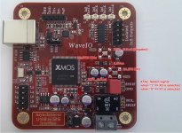
So it's attached to my current message. WaveIO only accept 22.5792 and 24.576 MHz external master clock wired directly to the red pads marked marked with the specific freqs.! The control signal you can take it from opposite pads: it can be found in 'true' and 'negated' form thus you can choose whatever signal you need!
As a small advice: there's a multiplexer on WaveIO (U7) which will choose between clock signals generated by X1 and X3 parts. To keep things simple, one can solder the output of your clock generator to both of the multiplexer's inputs (marked with "22.5792 MHz" and "24.576 MHz" red text) basically shorting them together while transporting the signal using only one coax cable. One additional note: all signals are not isolated from the main board so GND connection would be necessary. If you can isolate the Master Clock output then you might need to use a small optocoupler (or other cheap isolator) for clock selection signal sourcing by WaveIO.
Feel free to contact me here for additional support, if needed (it's easier for me to respond)!
Kind regards,
L
Attachments
Last edited:
Thanks Lucian and Andrea for that, I was asking myself this question as I plan to use Lucian's device.
So we can feed it without removing the NDKs before ?
So we can feed it without removing the NDKs before ?
I will access a Agilent E5052 at university lab.
See post #270 in AMC184 thread at http://www.diyaudio.com/forums/group-buys/196817-discrete-low-jitter-clock-gb-27.html
That's fine Andrea, I know that your are a serious guy. My memory is really bad and I knew that you had also a german relation with sota measurements instruments and had already measured a Laptech.
My entries above was just to know as well if Laptek has a concistency with its products !
Bah, as we say in France : "a walking fool goes always further than a seated inttelectual"😀 . Not than I think you're a fool (I think exactly the opposite) but a man who work, learn and share is always going further, better than a guy who says" you have to know I really hate you guys"... Jocko's ? (took from the famous Lee general ?).
Well I'm with you, if the clock is worst than a oven clock or a NDK/SI one... it's my risk 🙂.
Thank you for sharing.
Sadly no! You have to remove both of the NDK parts (which is something that I'm worried about!) and wire Andrea's clock(s) externally to any of the free pads you're comfortable with! There will two for each connection provided by both NDK footprints and by a generic 5 x 7 mm oscillator.. which wasn't used for a long time!Thanks Lucian and Andrea for that, I was asking myself this question as I plan to use Lucian's device.
So we can feed it without removing the NDKs before ?
Kind regards,
L
Shane, Acko
as you know SC-cut crystal needs an oven to work, so the project become more complex. That's the reason I have chosen AT-cut crystal.
I think this is a valid question for Laptech. SC crystals are less frequency stable at room teperature but thats a minor issue. I really don't think anyone could hear a frequency error of 100 PPM.
SC crystals are usually higher Q and can run at higher drive levels would make for lower phase noise.
Crystal Technology
Current Handling:
This refers to the maximum current at which a resonator can be operated without a significant (reversible) change in frequency. Generally, this is markedly higher for SC-cut than for AT-cut resonators. The consequences for oscillator applications are an improved phase noise floor by operating a higher current, and reduced sensitivity to drive level change, which may affect aging of the oscillator frequency.
I think this is a valid question for Laptech. SC crystals are less frequency stable at room teperature but thats a minor issue. I really don't think anyone could hear a frequency error of 100 PPM.
SC crystals are usually higher Q and can run at higher drive levels would make for lower phase noise.
Crystal Technology
Attached a quote from the israeli Nofech for a 11.2896 MHz 3rd overtone Sc-cut crystal.
The Q factor of the crystal increases up to 1M and more.
Unit price is more than double.
I will ask Laptech for the same as above, I expect their crystals were a little less expensive than the Nofech one, but not much.
BTW, 3rd/5th overtone Sc-cut crystal will be the first choise to develop the Driscoll oscillator.
Attachments
Andrea,
is my perception correct that the Lap-Tech xtal have a 3ppm frequency accuracy versus 1,5ppm for the Nofech? Is it your intention to ask Lap-Tech for a selection with better accuracy than their standard production offers? I'd like that very much...
is my perception correct that the Lap-Tech xtal have a 3ppm frequency accuracy versus 1,5ppm for the Nofech? Is it your intention to ask Lap-Tech for a selection with better accuracy than their standard production offers? I'd like that very much...
I think this is a valid question for Laptech. SC crystals are less frequency stable at room teperature but thats a minor issue. I really don't think anyone could hear a frequency error of 100 PPM.
SC crystals are usually higher Q and can run at higher drive levels would make for lower phase noise.
Crystal Technology
Attached a quote from the israeli Nofech for a 11.2896 MHz 3rd overtone Sc-cut crystal.
The Q factor of the crystal increases up to 1M and more.
Unit price is more than double.
I will ask Laptech for the same as above, I expect their crystals were a little less expensive than the Nofech one, but not much.
BTW, 3rd/5th overtone Sc-cut crystal will be the first choise to develop the Driscoll oscillator.
With all due respect, I think this is re inventing the wheel - I have discussed
this with Andrea previously.
My suggestion - source an Asian supplier of SC-cut VL Phase Noise 45/49
MHz OCXO's and design a divider board to get all the frequencies required
by good folks here.
Looking at phase noise specs of VHQ 45MHz OCXO's like Pulsar (Russian),
by dividing down to 11.2896MHz you will end up with very similar phase noise specs to a native (undivided) 11.2896 clock if it is done well.
Given the quantities generated by a/ a group buy and b/ the use of common
base freq OCXO you will get these pretty cheap and you could most likely
even have some input into the design. They will be very interested in building quantities of 100 or so OCXO's for you.
Just my 2 cents. 🙂
ZZZ
Andrea,
is my perception correct that the Lap-Tech xtal have a 3ppm frequency accuracy versus 1,5ppm for the Nofech? Is it your intention to ask Lap-Tech for a selection with better accuracy than their standard production offers? I'd like that very much...
Its easy to add a trimmer cap to adjust the frequency to your target. The drift may be important in some apps but as I said not for audio playback. You would need a good reference to even gauge its frequency and its drift.
With all due respect, I think this is re inventing the wheel - I have discussed
this with Andrea previously.
My suggestion - source an Asian supplier of SC-cut VL Phase Noise 45/49
MHz OCXO's and design a divider board to get all the frequencies required
by good folks here.
ZZZ
But that eliminates the fun of building analog circuits that can be really touchy to get working. . .
Its certainly a valid idea. There are at least two Russian vendors with
really good oscillators that should be in the $100 range. Real SOTA oscillators are in the $500-$6000 range and probably overkill.
Dividing down vs a PLL locking to a lower frequency I think is still an open question. Typical high performance applications use the PLL method.
Andrea,
is my perception correct that the Lap-Tech xtal have a 3ppm frequency accuracy versus 1,5ppm for the Nofech? Is it your intention to ask Lap-Tech for a selection with better accuracy than their standard production offers? I'd like that very much...
As Demian said, exact frequency and long term stability are not great issues in digital audio.
But that eliminates the fun of building analog circuits that can be really touchy to get working. . .
I agree 100%. This is a diy forum and our fun is just to experiment, even if we can find on the market the finished project.
Just for experimenting, the Butler and the Driscoll oscillators, with the crystal in the emitter circuit (the crystal see very low impedance), have the ability to reach very high loaded Q, sometimes very close to the unloaded Q of the crystal. This not ensure itself a very low phase noise oscillator, but helps a lot.
So, as you can see in the Nofech quote, an Sc-cut crystal usually shows a very high Q, almost an order of magnitude than an AT-cut crystal. Working at 3rd harmonic helps to increase the Q of the crystal.
Obviously, there are other issues, such as the flicker noise of the active device (that's the reason to use a low noise BJT), the noise coming from the power supply (that affects strongly the performance of an oscillator in the close to the carrier region), and so on. But the high Q of the crystal is the minimum starting point.
Updating - First batch closed
Crystals have been ordered and paid. Hope they will ship within the end of February.
Since I have already paid for the crystal, please complete the payment request I have sent through Paypal.
Members having still to pay:
AR2
myint67
ryanj
Please, confirm the payment as soon as possible.
There are also the following members that ask for the assembly service (in the order form I received), but Phil (korben69) has not been advised about:
thorstenlarsen
noizas
hirez69
zenelectro
JethroTull
triodehunter
Please, fill the assembly service document and submit it to Phil.
Please, wait ordering parts, because the final value of some components of the oscillator (3rd and 5th overtone crystals) have to be confirmed.
As soon as I will receive the crystals, I'll post the final BOM and assembly guide.
I will also check each crystal to start at the right harmonic.
Second batch
- Miklos: 1 x 16.9344 MHz
- Marlowe: 3 x 16.9344Mhz + 3 x 25MHz
- carz 1x 27MHz
- 1audio : 1X6.1440MHz
- mravinsky : 1 x 16.9344Mhz
- triodehunter: 1x 25.0000 MHz
- noizas : 2 x 16.9344 MHz
- randytsuch: 2x 25.0000 MHz
@andrea_mori:
Andrea - thanks for your work & effort ;-) ... Look forward to trying out the crystals when in due time things have been tested.
Greetings from a now snowy & winterclad Denmark,
Jesper
Crystals have been ordered and paid. Hope they will ship within the end of February.
Andrea - thanks for your work & effort ;-) ... Look forward to trying out the crystals when in due time things have been tested.
Greetings from a now snowy & winterclad Denmark,
Jesper
- Status
- Not open for further replies.
- Home
- Source & Line
- Digital Line Level
- The Well Tempered Master Clock - Building a low phase noise/jitter crystal oscillator