Hi,
.. this probably is a question to andrea_mori: This looks really interesting but I do not yet know which frequencies I need. Can you say when you intend/suppose to close the "join-in" on your crystal & PCB buying?
Cheers,
Jesper
Now I'm designing the daughter board PCB.
I'm thinking to close the list as soon as the PCB will be ready, then I will ask Laptech for a quote.
I believe within the end of november.
Andrea
Jitter only really matters on D/A and A/D conversion. On digital signals it matters only if there is enough of it to cause bit errors, which is really uncommon. XO near DAC chip is optimal...
Also I don't specially like UFL : they're annoying to use, fragile, and the shielding effectiveness is bad at audio frequencies (thin shield). It is much better than the usual wires flying everywhere, but if you really want some coax, get plumbing pipe, or the bare cable from ebay and solder your favourite connectors.
Nothing in stock, sorry.
Peufeu,or did you find this document http://www.millertechinc.com/pdf_fi...nd shielding effectiveness_files/image006.jpg ,please?
UFL connector is present on alot of board(Fifo,Acko board),the largest cable that can be mounted on UFL is the RG178.
It is possible to improve the UFL with copper strip 1181 TAPE (1/2) 3M Electronic Specialty | Mouser ,What do you think?
Now I'm designing the daughter board PCB.
I'm thinking to close the list as soon as the PCB will be ready, then I will ask Laptech for a quote.
I believe within the end of november.
Andrea
Thanks for the info, Andrea ;-)
Jesper
I notice every time you misspell my nick 🙁
Sorry Esgigt; no offense from me, I suffer from dyslexia because my eyes on DIYA are not too much focused on words but more involved by understanding the phrases structure to translate + a very bad english as most french (here we don't learn english when we are young with TV cartoons like in your country... politics are a "little" conservative !
 I do the best i can and know I'm hard to read for english people (thanks for patience !).
Maybe also my glasses needs to be changed 😀
Well about vibrations :
at First Audio : Younger when we tweaked old Philips players I saw than put the XO can to Gnd could improve sometimes the sound ?! Why I don't know.
Do you advise a good coupling of the DAC cabinet on a hard and heavy stone or heavy wood. Some Blue Tack around the XO Can ? But the heat ? Does the can of the Xo is involved to let the XO cooler (heat= drift ?).
Read also that the aging of the Crystal during the first year can not be avoided. But after the PPM aging/year is very low... Well the phase noise is certainly more important for the listening result than a stable frequency I surmise...🙂 Remind me all the effort to have stable speed with turnables... nostalgy !
OK, now I understand... 😉 I won't mind in future...Sorry Esgigt; no offense from me, I suffer from dyslexia because my eyes on DIYA are not too much focused on words but more involved by understanding the phrases structure to translate + a very bad english as most french (here we don't learn english when we are young with TV cartoons like in your country... politics are a "little" conservative !
Maybe also my glasses needs to be changed 😀
Well about vibrations :
at First Audio : Younger when we tweaked old Philips players I saw than put the XO can to Gnd could improve sometimes the sound ?! Why I don't know.
Do you advise a good coupling of the DAC cabinet on a hard and heavy stone or heavy wood. Some Blue Tack around the XO Can ? But the heat ? Does the can of the Xo is involved to let the XO cooler (heat= drift ?).
Read also that the aging of the Crystal during the first year can not be avoided. But after the PPM aging/year is very low... Well the phase noise is certainly more important for the listening result than a stable frequency I surmise...🙂 Remind me all the effort to have stable speed with turnables... nostalgy !
You ask about heat... I remember asking Andrea about the same issue (need for temperature-control) some time ago. He answered me that it was of less importance...
I guess that long-term differences like ageing won't affect the SQ. Mainly short-term fluctuations will....
UFL connector is present on alot of board(Fifo,Acko board),the largest cable that can be mounted on UFL is the RG178.
I think the primary purpose of UFL jumpers for DIY audio is to prevent people who don't know about EMI from using flying wires everywhere for their I2S and clocks. Any coax is going to be something like 100000 times better (like 100dB) than a mess of flying wires... or ribbon cable with only 1 GND wire. In this respect it is a success ! And it looks neat. Don't worry about it. Just don't touch it too much as it is very fragile.
Hi Peufeu,
If no UF.L wires is there some thin coax advised on the main web vendor ? Need to be 50 ohms and on the pcb layout a gnd hole near each I2S signal (return current will find its way ?). I see many good pcbs wasted by a GSSSS when it comes to export I2S signals... I mean better a dedicated path for return signal to th eemmiter I2S chip if no continuous grounding plane...).
@ Essigt, That's horrible what you said about heat in a precedent post, with dyslexia I suffer from memory problem also😀
Hi all,
Knowing that this is a slight digression I noticed that you have discussed the PSU for this clock circuitry. To that end I did some noise measurements on a couple of batteries the other day (A123Systems & SLA) and have posted the results here ...
http://www.diyaudio.com/forums/powe...listened-li-ion-batteries-12.html#post4117260
Please note that I thread carefully here - just FYI.
Jesper
@ Essigt, That's horrible what you said about heat in a precedent post, with dyslexia I suffer from memory problem also😀
Spot-on... Horrible is my middle-name
 sorry for the inconvenience..
Hi all,
Knowing that this is a slight digression I noticed that you have discussed the PSU for this clock circuitry. To that end I did some noise measurements on a couple of batteries the other day (A123Systems & SLA) and have posted the results here ...
http://www.diyaudio.com/forums/powe...listened-li-ion-batteries-12.html#post4117260
Please note that I thread carefully here - just FYI.
Jesper
Hi Jesper,
I usually prefer linear regulators, but if someone will give a test comparison against batteries I would be very curious.
The oscillator needs 15V and 3.3V, so starting from 1.2V cells one can feed it by 3.6V and 14.4V or 15.6V.
The daughter board provides both Demian's low noise regulators and headers to connect external DC supply.
Andrea
Hi Andrea,
A quick comment to this (I thought ;-)):
LiFePO4 batteries have a "maximum" recommended cycle charge voltage of 3.6 volts and a suggested float voltage of about 3.45 volts. So I reckon they could be used directly for many digital circuits (do so myself). I'm currently trying out li-ion batteries at a float voltage of about 4 volts to see if they will sustain this for a longer period of time. So far it looks fine although balancing is needed for every cell.
To my knowledge there's not much information available about li-ion batteries and running them at floating voltages ... I briefly communicated with the owner of Basic to Advanced Battery Information from Battery University about this a couple of years ago and at that point in time he didn't know of any sources on float charging li-ion batteries. However, what seems to diminish the life-span of li-ion batteries being float charged is temperature variations (which leads to voltage fluctuations) and voltage variations on the charger. LiFePO4 batteries apparently are (much) more robust in this respect and, as I mentioned, have a suitable voltage level for digital electronics.
So, no more digressions on batteries ...
Greetings from up north ;-)
Jesper
A quick comment to this (I thought ;-)):
The oscillator needs 15V and 3.3V, so starting from 1.2V cells one can feed it by 3.6V and 14.4V or 15.6V.
LiFePO4 batteries have a "maximum" recommended cycle charge voltage of 3.6 volts and a suggested float voltage of about 3.45 volts. So I reckon they could be used directly for many digital circuits (do so myself). I'm currently trying out li-ion batteries at a float voltage of about 4 volts to see if they will sustain this for a longer period of time. So far it looks fine although balancing is needed for every cell.
To my knowledge there's not much information available about li-ion batteries and running them at floating voltages ... I briefly communicated with the owner of Basic to Advanced Battery Information from Battery University about this a couple of years ago and at that point in time he didn't know of any sources on float charging li-ion batteries. However, what seems to diminish the life-span of li-ion batteries being float charged is temperature variations (which leads to voltage fluctuations) and voltage variations on the charger. LiFePO4 batteries apparently are (much) more robust in this respect and, as I mentioned, have a suitable voltage level for digital electronics.
So, no more digressions on batteries ...
Greetings from up north ;-)
Jesper
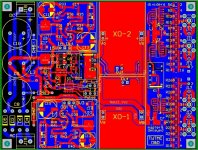
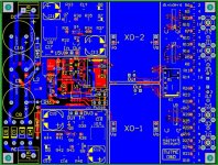
Daughter board PCB
Attached the daughter board PCB layout.
I have checked several times the PCB, but if you find any errors please let me know (Demian please take a look).
Board size is 3.25" x 4.25", it accommodates 2 XOs.
Attached the daughter board PCB layout.
I have checked several times the PCB, but if you find any errors please let me know (Demian please take a look).
Board size is 3.25" x 4.25", it accommodates 2 XOs.
Attachments
Attached the daughter board final schematic and the part list.
The daughter board is fully configurable.
It accommodates 2 Xos, but you can use it for a single XO.
It implements some dividers (optionally): 2/4/8/16.
It outputs master clock directly, but there are also 3 delayed clock.
It provides rectification and filtering from AC, but one can use an external DC supply.
There are 2 low noise regulators on board (15V and 3V3), but it's also possible to use external regulators.
Optionally, you can power off the oscillator not used at a time by fitting a second relay.
Two switching mode between the 2 XOs are provided: pulse mode and fixed mode.
U.fl. sockets, SMA sockets and pin strips are provided as output connection.
Attachments
- andrea_mori : 2 x 5.6448MHz + 2 x 11.2896MHz + 1 X 22.5792 MHz + 1 x 24.576 MHz + 1 x 45.1584 MHz + 1 x 49.152 MHz + 10 x PCB + 4 x daughter board PCB
- Eldam : 1 x 11.2896 Mhz + 4 x PCB
- esgigt : 1 x 11.2896 Mhz + 1 x PCB, soldered if possible
- fralippo : 1 x 22.5792 MHz and 1 x 24.576 MHz + 2 x PCB + 1 x daughter board PCB
- mravinsky : 2 x 11.2896 Mhz + 1 x PCB
- TNT : 1x22.5792MHz 1x24.5760MHz + 2 x PCB, soldered if possible
- 1audio : 2x22.5792MHz 2x24.5760MHz + 2 x PCB + daughter board.
- randytsuch : 2x25.0000MHz + 4 x PCB
- TNT or maybe : 1 x 11.2896 Mhz + 1 x PCB, soldered if possible
- myint67 : 1x11.2896mhz + 1pcb also soldered if possible
- EdwardTam : 2x 16.9344MHz + 1 x 11.2896 Mhz + 2x PCB
- BDL : 1 x 11.2896 MHz + 2 x PCB + 1 x daughter board PCB
- thorstenlarsen : 2 x 11.2896 MHz + 2 x PCB
- Zoran : 1x22.5792MHz 1x24.5760MHz + 2 x PCB, (soldered or not...)
- walangalam : 1 x 11.2896 Mhz + 2 x PCB
- AR2: 1 x 22.5792 MHz and 1 x 24.576 MHz + 2 x PCB (soldering not needed)
- mcluxun: 1 x 22.5792 MHz and 1 x 24.576 MHz 1 x 45.1584 MHz + 1 x 49.152 MHz+ 2 x PCB (soldering if possible)
- damohpi: 1 x 11.2896 + 1x PCB unsoldered
- noizas : 2 x 5.6448MHz + 2 x 11.2896MHz + 4 x PCB
- badrisuper : : 1 x 11.2896 Mhz + 2 x PCB
- Clsidxxl: 1 x 45.1584 MHz + 1 x 49.152 MHz+daughter board + 2 x PCB (soldering if possible)
- zeta4 1x 22.5792Mhz + 1 x PCB (soldering not needed)
- chertk : 1 x 22.5792 MHz and 1 x 24.576 MHz + 2 x PCB + 1 x daughter board
- hirez69: 1 x 22.5792 MHz and 1 x 24.576 MHz + 1 x 45.1584 MHz + 1 x 49.152 MHz + 4 x PCB (soldered) + 1 x daughter board[/QUOTE]
- palmito : 1 x 22.5792MHz 1 x 24.5760MHz + 1 x PCB + daughter board.
- andrea_mori : 2 x 5.6448MHz + 2 x 11.2896MHz + 1 X 22.5792 MHz + 1 x 24.576 MHz + 1 x 45.1584 MHz + 1 x 49.152 MHz + 10 x PCB + 4 x daughter board PCB
- Eldam : 1 x 11.2896 Mhz + 4 x PCB
- esgigt : 1 x 11.2896 Mhz + 1 x PCB, soldered if possible
- fralippo : 1 x 22.5792 MHz and 1 x 24.576 MHz + 2 x PCB + 1 x daughter board PCB
- mravinsky : 2 x 11.2896 Mhz + 1 x PCB
- TNT : 1x22.5792MHz 1x24.5760MHz + 2 x PCB, soldered if possible
- 1audio : 2x22.5792MHz 2x24.5760MHz + 2 x PCB + daughter board.
- randytsuch : 2x25.0000MHz + 4 x PCB
- TNT or maybe : 1 x 11.2896 Mhz + 1 x PCB, soldered if possible
- myint67 : 1x11.2896mhz + 1pcb also soldered if possible
- EdwardTam : 2x 16.9344MHz + 1 x 11.2896 Mhz + 2x PCB
- BDL : 1 x 11.2896 MHz + 2 x PCB + 1 x daughter board PCB
- thorstenlarsen : 2 x 11.2896 MHz + 2 x PCB
- Zoran : 1x22.5792MHz 1x24.5760MHz + 2 x PCB, (soldered or not...)
- walangalam : 1 x 11.2896 Mhz + 2 x PCB
- AR2: 1 x 22.5792 MHz and 1 x 24.576 MHz + 2 x PCB (soldering not needed)
- mcluxun: 1 x 22.5792 MHz and 1 x 24.576 MHz 1 x 45.1584 MHz + 1 x 49.152 MHz+ 2 x PCB (soldering if possible)
- damohpi: 1 x 11.2896 + 1x PCB unsoldered
- noizas : 2 x 5.6448MHz + 2 x 11.2896MHz + 4 x PCB
- badrisuper : : 1 x 11.2896 Mhz + 2 x PCB
- Clsidxxl: 1 x 45.1584 MHz + 1 x 49.152 MHz+daughter board + 2 x PCB (soldering if possible)
- zeta4 1x 22.5792Mhz + 1 x PCB (soldering not needed)
- chertk : 1 x 22.5792 MHz and 1 x 24.576 MHz + 2 x PCB + 1 x daughter board
- hirez69: 1 x 22.5792 MHz and 1 x 24.576 MHz + 1 x 45.1584 MHz + 1 x 49.152 MHz + 4 x PCB (soldered) + 1 x daughter board[/QUOTE]
- palmito : 1 x 22.5792MHz 1 x 24.5760MHz + 1 x PCB + daughter board.
- gentlevoice: 1 x 49.152 1 x 6.144 MHz 1 x 24.576 MHz + 1 x PCB
- andrea_mori : 2 x 5.6448MHz + 2 x 11.2896MHz + 1 X 22.5792 MHz + 1 x 24.576 MHz + 1 x 45.1584 MHz + 1 x 49.152 MHz + 10 x PCB + 4 x daughter board PCB
- Eldam : 1 x 11.2896 Mhz + 4 x PCB
- esgigt : 1 x 11.2896 Mhz + 1 x PCB, soldered if possible
- fralippo : 1 x 22.5792 MHz and 1 x 24.576 MHz + 2 x PCB + 1 x daughter board PCB
- mravinsky : 2 x 11.2896 Mhz + 1 x PCB
- TNT : 1x22.5792MHz 1x24.5760MHz + 2 x PCB, soldered if possible
- 1audio : 2x22.5792MHz 2x24.5760MHz + 2 x PCB + daughter board.
- randytsuch : 2x25.0000MHz + 4 x PCB
- TNT or maybe : 1 x 11.2896 Mhz + 1 x PCB, soldered if possible
- myint67 : 1x11.2896mhz ,1x22.5792+ 2pcb ,1 xdaughter board , soldered if possible
- EdwardTam : 2x 16.9344MHz + 1 x 11.2896 Mhz + 2x PCB
- BDL : 1 x 11.2896 MHz + 2 x PCB + 1 x daughter board PCB
- thorstenlarsen : 2 x 11.2896 MHz + 2 x PCB
- Zoran : 1x22.5792MHz 1x24.5760MHz + 2 x PCB, (soldered or not...)
- walangalam : 1 x 11.2896 Mhz + 2 x PCB
- AR2: 1 x 22.5792 MHz and 1 x 24.576 MHz + 2 x PCB (soldering not needed)
- mcluxun: 1 x 22.5792 MHz and 1 x 24.576 MHz 1 x 45.1584 MHz + 1 x 49.152 MHz+ 2 x PCB (soldering if possible)
- damohpi: 1 x 11.2896 + 1x PCB unsoldered
- noizas : 2 x 5.6448MHz + 2 x 11.2896MHz + 4 x PCB
- badrisuper : : 1 x 11.2896 Mhz + 2 x PCB
- Clsidxxl: 1 x 45.1584 MHz + 1 x 49.152 MHz+daughter board + 2 x PCB (soldering if possible)
- zeta4 1x 22.5792Mhz + 1 x PCB (soldering not needed)
- chertk : 1 x 22.5792 MHz and 1 x 24.576 MHz + 2 x PCB + 1 x daughter board
- hirez69: 1 x 22.5792 MHz and 1 x 24.576 MHz + 1 x 45.1584 MHz + 1 x 49.152 MHz + 4 x PCB (soldered) + 1 x daughter board[/QUOTE]
- palmito : 1 x 22.5792MHz 1 x 24.5760MHz + 1 x PCB + daughter board.
- gentlevoice: 1 x 49.152 1 x 6.144 MHz 1 x 24.576 MHz + 1 x PCB
- andrea_mori : 2 x 5.6448MHz + 2 x 11.2896MHz + 1 X 22.5792 MHz + 1 x 24.576 MHz + 1 x 45.1584 MHz + 1 x 49.152 MHz + 10 x PCB + 4 x daughter board PCB
- Eldam : 1 x 11.2896 Mhz + 4 x PCB
- esgigt : 1 x 11.2896 Mhz + 1 x PCB, soldered if possible
- fralippo : 1 x 22.5792 MHz and 1 x 24.576 MHz + 2 x PCB + 1 x daughter board PCB
- mravinsky : 2 x 11.2896 Mhz + 1 x PCB
- TNT : 1x22.5792MHz 1x24.5760MHz + 2 x PCB, soldered if possible
- 1audio : 2x22.5792MHz 2x24.5760MHz + 2 x PCB + daughter board.
- randytsuch : 2x25.0000MHz + 4 x PCB
- TNT or maybe : 1 x 11.2896 Mhz + 1 x PCB, soldered if possible
- myint67 : 1x11.2896mhz ,1x22.5792+ 2pcb ,1 xdaughter board , soldered if possible
- EdwardTam : 2x 16.9344MHz + 1 x 11.2896 Mhz + 2x PCB
- BDL : 1 x 11.2896 MHz + 2 x PCB + 1 x daughter board PCB
- thorstenlarsen : 2 x 11.2896 MHz + 2 x PCB
- Zoran : 1x22.5792MHz 1x24.5760MHz + 2 x PCB, (soldered or not...)
- walangalam : 1 x 11.2896 Mhz + 2 x PCB
- AR2: 1 x 22.5792 MHz and 1 x 24.576 MHz + 2 x PCB (soldering not needed)
- mcluxun: 1 x 22.5792 MHz and 1 x 24.576 MHz 1 x 45.1584 MHz + 1 x 49.152 MHz+ 2 x PCB (soldering if possible)
- damohpi: 1 x 11.2896 + 1x PCB unsoldered
- noizas : 2 x 5.6448MHz + 2 x 11.2896MHz + 4 x PCB
- badrisuper : : 1 x 11.2896 Mhz + 2 x PCB
- Clsidxxl: 1 x 45.1584 MHz + 1 x 49.152 MHz+daughter board + 2 x PCB (soldering if possible)
- zeta4 1x 22.5792Mhz + 1 x PCB (soldering not needed)
- chertk : 1 x 22.5792 MHz and 1 x 24.576 MHz + 2 x PCB + 1 x daughter board
- hirez69: 1 x 22.5792 MHz and 1 x 24.576 MHz + 1 x 45.1584 MHz + 1 x 49.152 MHz + 4 x PCB (soldered) + 1 x daughter board[/QUOTE]
- palmito : 1 x 22.5792MHz 1 x 24.5760MHz + 1 x PCB + daughter board.
- gentlevoice: 1 x 49.152 1 x 6.144 MHz 1 x 24.576 MHz + 1 x PCB
- naimster: 1 x 22.5792 MHz and 1 x 24.576 MHz + 2 x PCB (soldering if possible)
Whats the price of a soldered clock pcb?
Hi Ake,
please see post #36 for the estimated cost.
Andrea
- andrea_mori : 2 x 5.6448MHz + 2 x 11.2896MHz + 1 X 22.5792 MHz + 1 x 24.576 MHz + 1 x 45.1584 MHz + 1 x 49.152 MHz + 10 x PCB + 4 x daughter board PCB
- Eldam : 1 x 11.2896 Mhz + 4 x PCB
- esgigt : 1 x 11.2896 Mhz + 1 x PCB, soldered if possible
- fralippo : 1 x 22.5792 MHz and 1 x 24.576 MHz + 2 x PCB + 1 x daughter board PCB
- mravinsky : 2 x 11.2896 Mhz + 1 x PCB
- TNT : 1x22.5792MHz 1x24.5760MHz + 2 x PCB, soldered if possible
- 1audio : 2x22.5792MHz 2x24.5760MHz + 2 x PCB + daughter board.
- randytsuch : 2x25.0000MHz + 4 x PCB
- TNT or maybe : 1 x 11.2896 Mhz + 1 x PCB, soldered if possible
- myint67 : 1x11.2896mhz ,1x22.5792+ 2pcb ,1 xdaughter board , soldered if possible
- EdwardTam : 2x 16.9344MHz + 1 x 11.2896 Mhz + 2x PCB
- BDL : 1 x 11.2896 MHz + 2 x PCB + 1 x daughter board PCB
- thorstenlarsen : 2 x 11.2896 MHz + 2 x PCB
- Zoran : 1x22.5792MHz 1x24.5760MHz + 2 x PCB, (soldered or not...)
- walangalam : 1 x 11.2896 Mhz + 2 x PCB
- AR2: 1 x 22.5792 MHz and 1 x 24.576 MHz + 2 x PCB (soldering not needed)
- mcluxun: 1 x 22.5792 MHz and 1 x 24.576 MHz 1 x 45.1584 MHz + 1 x 49.152 MHz+ 2 x PCB (soldering if possible)
- damohpi: 1 x 11.2896 + 1x PCB unsoldered
- noizas : 2 x 5.6448MHz + 2 x 11.2896MHz + 4 x PCB
- badrisuper : : 1 x 11.2896 Mhz + 2 x PCB
- Clsidxxl: 1 x 45.1584 MHz + 1 x 49.152 MHz+daughter board + 2 x PCB (soldering if possible)
- zeta4 1x 22.5792Mhz + 1 x PCB (soldering not needed)
- chertk : 1 x 22.5792 MHz and 1 x 24.576 MHz + 2 x PCB + 1 x daughter board
- hirez69: 1 x 22.5792 MHz and 1 x 24.576 MHz + 1 x 45.1584 MHz + 1 x 49.152 MHz + 4 x PCB (soldered) + 1 x daughter board[/QUOTE]
- palmito : 1 x 22.5792MHz 1 x 24.5760MHz + 1 x PCB + daughter board.
- gentlevoice: 1 x 49.152 1 x 6.144 MHz 1 x 24.576 MHz + 1 x PCB
- naimster: 1 x 22.5792 MHz and 1 x 24.576 MHz + 2 x PCB (soldering if possible)
- zenelectro : 1 x 45.1584 MHz + 1 x 49.152 MHz + 2 x PCB's + 1 x daughterboard (soldered if possible)
- Status
- Not open for further replies.
- Home
- Source & Line
- Digital Line Level
- The Well Tempered Master Clock - Building a low phase noise/jitter crystal oscillator