The Pierce is claimed to be the best oscillator for fundamental crystals, up to 20-25 MHz. I could add it to my list of testing, with my very very long time...
*************************************
Hello Andrea.
Believe me...I know how difficult it is to get time for these kind of activities...
Some more input on the subject of Pierce vs Clapps:
The Pierce oscillator looks very similar to Colpitts type of oscillators.
There are major differences however, that might have someting to do with its remarkable
performance.
The Colpitts/Clapp operates in class C.
It uses the resonator as a filter element.
The resultant current through the sustainer (due to its class of operation) contains
high amounts of harmonics that influence the peripherial circuitry.
The Pierce operates in class A.
It uses the resonator as a feedback element.
The current through the sustainer in the Pierce contains no harmonics.
Because the resonator is used as a feedback element, it has very good
parameters (low noise, low THD, low sensitivity to PSU, etc) at the
resonant frequency.
It is a very easy design to build. It is highly stable.
I dont think you need much time to build this one..
Cheers...
I had to lookup this one. Appears to be the "common" oscillator-circuit used in IC's... like the TDA1541A.#Pierce Oscillator#
@Herbert: I'm curious to the noise-figures too... But from the way you're asking, I guess it will not stand the comparisson to the TWTMC
I had to lookup this one. Appears to be the "common" oscillator-circuit used in IC's... like the TDA1541A.
@Herbert: I'm curious to the noise-figures too... But from the way you're asking, I guess it will not stand the comparisson to the TWTMC
************************************
Thank you esgigt for your response.
Interesting question.... Although not easy to answer to.
The Pierce oscillator I referred to was designed and used - many years ago - in a project, where
frequencies are much higher, and close-in PN is of little interest.
As mentioned earlier, it is not easy to do MUCH better (in terms of close-in PN) than the measurement
data presented here.
The objective behind this thread (according to my understanding) is to investigate various, simple
oscillator circuits, and find the one with the most suitable parameters for Digital Audio
(close-in PN, low modulation-conversion-rate, etc).
I find the oscillator presented here (Rutgers oscillator), equipped with the Laptech crystal, to be
an excellent oscillator for digital audio.
Similar to all triple-node oscillators, the Pierce is highly stable, and its performance is absolutely remarkable.
It possesses features that make it - at the very least - worthwhile for testing.
I don't remember any exact numbers to quote, and those would still be irrelevant here, as the design objective, the active
components, the resonator, and the final circuit used were all very different and particular for the application.
Keep up the good work, Gentlemen.
Last edited:
Hi Alexiss & all,
I have a suggestion/an offer relative to the Pierce oscillator you mention.
If you/one of you can draw up a schematic for a 24.576 MHz Pierce oscillator (which could also be of interest to me personally) I will make a PCB layout (for you to comment on if you so wish), make the PCB (70um copper, ~0.2mm base material thickness, FR4, "hand made vias") and mount it with the best possible components for this purpose (some advice will be needed here on critical components).
If ok with Andrea I will then send it to him so that he can include it in the measurement sequence together with the other oscillators. Or I can send it to e.g. Gerhard or one of those here with access to a PN measurement device ...
Please let me know if this is interesting to you/Andrea/others here.
Cheers from Denmark,
Jesper
I like that idea, Jesper.
It could give us more insight into the usability of the diverse oscillator designs in audio.
I hope Andrea is willing to cooperate...
It could give us more insight into the usability of the diverse oscillator designs in audio.
I hope Andrea is willing to cooperate...
Hi Alexiss & all,
.... draw up a schematic for a 24.576 MHz Pierce oscillator (which could also be of interest to me personally) I will make a PCB layout and mount it with the best possible components for this purpose (some advice will be needed here on critical components).
.....
Jesper
**********************************
Hello Jesper and esgigt, and thank you for your responses.
...Certainly a noble idea....
If you ever have the time, please read the document titled ”Reproducible Low Noise oscillators” from Herbert.
It covers some theory and design principles behind his oscillator.
(The dutch version is much better, as dutch is close to swedish).
It is clear that merely ”putting a schematics together” will not yield any improvements over the Rutgers oscillator.
Since the Pierce is one of the triple--node-oscillators, you won't need a new PCB to test it.
You can use the existing TWTMC-C pcb.
This modification (Clapps-Pierce) should preferably be performed by the designer (Herbert or Andrea), since the AGC in
the Rutgers-design won't work in the Pierce schematics.
It was my initial plan (when I ordered xtals from Andrea) to do something similar to what you suggested.
That is, make a Pierce and ask Andrea to perform PN measurements on it.
Herbert has mentioned earlier that he has tried almost all fundamental oscillator circuits and found the Clapps
to be the best one.
I respect his comments 100%.
I have really enjoyed reading his articles that he has kindly shared with the rest of us (dank je, Herbert).
However, I am certain that a carefully-designed Pierce-oscillator will outperform all other fundamental oscillator circuits.
This is partially due to how the oscillator functions and how the xtal is used (read my previous post).
-----------------------------------
Keep up the good work, Gentlemen
Last edited:
I had to lookup this one. Appears to be the "common" oscillator-circuit used ....
Well esgigt.... there is a very good reason why

Last edited:
Hi Alexiss
All right - thanks for clarifying - and I will see if I will have time to read the document more thoroughly (quick-read it earlier) ... My main purpose in this also mainly was to possibly help with something that could reduce potential time used elsewhere, e.g. Andrea's time.
😕 🙄
Well ... then ... 😉
Cheers,
Jesper
If you ever have the time, please read the document titled ”Reproducible Low Noise oscillators” from Herbert.
It covers some theory and design principles behind his oscillator.
(The dutch version is much better ....
It is clear that merely ”putting a schematics together” will not yield any improvements over the Rutgers oscillator.
Since the Pierce is one of the triple--node-oscillators, you won't need a new PCB to test it.
You can use the existing TWTMC-C pcb.
All right - thanks for clarifying - and I will see if I will have time to read the document more thoroughly (quick-read it earlier) ... My main purpose in this also mainly was to possibly help with something that could reduce potential time used elsewhere, e.g. Andrea's time.
... as dutch is close to swedish ...
😕 🙄
Well ... then ... 😉
Cheers,
Jesper
Maybe, thinking to the Pierce oscillator, it worth to consider the simple way to get it work: one picogate unbuffered '04 only.
It works both with 5V and 3V3 (simply changing the chip), it doesn't need the squarer.
A few components only: 2 capacitors + 2 resistors.
Could be the quick way.
It works both with 5V and 3V3 (simply changing the chip), it doesn't need the squarer.
A few components only: 2 capacitors + 2 resistors.
Could be the quick way.
******************************************Maybe...........one picogate unbuffered '04 only, it doesn't need the squarer.
A few components only: 2 capacitors + 2 resistors.
Could be the quick way.
Hello Andrea and thank you for your response.
Yes, you are right....it is a deceptively simple circuit.
Done right - it has an amazing performance, showing the power of the Pierce circuit (class A sustainer, selective feedback via xtal, sine current waveform, near to series resonance).
It still requires a squarer since the output waveform won't be a nice square.
For example, it would be better to use only one gate of 74HC-U-04 for this circuit (guess which one), and leaving the other gates unused ;-)
After that, it would be possible to use whatever signal converter the designer wishes to choose for sine-to-square conversion.
I beleive the Pierce Oscillator to be technologically superior to all other triple-node-oscillators.
Believe it or not, it served as the basis for one of HPs most popular, Laboratory Frequency Reference Oscillators.
It is truely a remarkable circuit.
Unfortunately its superiority has become its Achilles heel.
Its excellent performance has promoted its overwhelming use as Gated Oscillators in ICs.
IC designers have not since cared about its performance, and this has led to its slow downfall into memorial abyss.
Last edited:
I developed my oscillator already many years ago!!
Read:
https://www.by-rutgers.nl/PDFiles/Reproducible Low Noise Oscillators.pdf
https://www.by-rutgers.nl/rutgerS-Clock.html
https://www.by-rutgers.nl/PDFiles/DC-receiver.pdf
and if you could read Dutch:
https://www.by-rutgers.nl/PDFiles/De Beste Oscillator.pdf
https://www.by-rutgers.nl/PDFiles/Beter Begrepen.pdf
https://www.by-rutgers.nl/PDFiles/De Beste Xtal-oscillator.pdf
Herbert.
These are all great, but specifically regarding the DC-receiver with an interest in measuring phase noise in my home workshop, if I am reading this correctly: can I build two of the same oscillator circuit and use these to measure the phase noise with respect to eachother? That's to say: this can be done without a 'known good' oscillator? I need to bootstrap the measuring device.
You absolutely can measure the phase noise if you have two. However for the close in stuff you need to phase lock the "reference" to the test oscillator. This will move the carrier to DC. At 90 degrees an balanced mixer will be the most sensitive. (Herberts oscillator won't lend itself since it has no active frequency trim). The actual noise of the oscillator would be -3 dB from the measured noise presuming they are essentially identical.
The other option is called the three corner hat. Take a third oscillator and measure the noise of each pairing. This allow you to derive a noise number for each oscillator by subtracting the numbers each pairing.
The third option is uses correlation with three oscillators and comparing two pairings, and removing the noise that not common to the two pairings. Need specific software. I think Hpworks can do this. (and two good balanced mixers and some other stuff).
.... (Herberts oscillator won't lend itself since it has no active frequency trim). ....
I am not sure....I think you can use this feature (the PLL input) in Herberts Reciever to lock-in.
Keep up the good work, Gentlemen.
Attachments
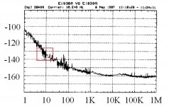
Phase Noise Measurements
Guys guys guys ...
Depending on what equipment you use, you'll get slightly different PN measurements.
I have attached PN measurements on HP's all time reference oscillator HP10811, and HP's BEST oscillator EVER made HPE1938A.
Please look at the attached graphs and read the PN data, at 10 Hz offset from the carrier:
HPE1938A......... appr -135 (dB)
HP10811........... appr -121 (dB)
RutgerS............ appr -132 (dB)
If you have a cravin for low PN figures @ close offset from the carrier big time - then look no further
than this one right here.
RutgerS performs almost as good as HPE1938A ! ! (at close offset from carrier). I find this absolutely astonishing.
I know many radio-enthusiasts build their own recievers to measure SSB PN, but the oscillators they
work with are most often LC-based oscillators.
Xtal-based oscillators - specially the good ones - like the Laptech - would seriously challenge the
performance of many hyper-expensive PN measurement equipment.
Guys... Measuring PN - at these low levels we're talkin about here, is really not a trivial
task....specially interpreting the gathered data...
cheers
Attachments

Last edited:
Thanks for sharing this !!!Phase Noise Measurements
Guys guys guys ...
Depending on what equipment you use, you'll get slightly different PN measurements.
I have attached PN measurements on HP's all time reference oscillator HP10811, and HP's BEST oscillator EVER made HPE1938A.
Please look at the attached graphs and read the PN data, at 10 Hz offset from the carrier:
HPE1938A......... appr -135 (dB)
HP10811........... appr -121 (dB)
RutgerS............ appr -132 (dB)
If you have a cravin for low PN figures @ close offset from the carrier big time - then look no further
than this one right here.
RutgerS performs almost as good as HPE1938A ! ! (at close offset from carrier). I find this absolutely astonishing.
I know many radio-enthusiasts build their own recievers to measure SSB PN, but the oscillators they
work with are most often LC-based oscillators.
Xtal-based oscillators - specially the good ones - like the Laptech - would seriously challenge the
performance of many hyper-expensive PN measurement equipment.
Guys... Measuring PN - at these low levels we're talkin about here, is really not a trivial
task....specially interpreting the gathered data...
cheers

So, hopefully I'm not to bold, stating that with the Rutgers oscillator or TWTMC one get's a state-of-the art oscillator 😉
....and with Rutgers oscillator or TWTMC one get's a state-of-the art oscillator 😉
If close-in PN is an important parameter for Digital Audio, and PN far-off the carrier has
no significance what so ever for Audio... then yes.
I am not sure about any of this myself, I think it does.
It is possible to improve the design, both in terms of close-in, and far-off the carrier PN, but that
requires measurement equipment capable of resolving that low...
...and with the measurements presented here...why would one bother??

I think it would be more fruitfull to not worry about the osillator itself, but maybe the PSU and
the sourrunding caps feeding the TWTMC clock.
I recall 1audio had posted a good PSU schematics in the beginning of this thread...
It will also be very interesting to see the results of the Driscoll oscillator measurements...
I might be mistakin...but if memory serves me right....I recall the Driscoll not being superior at close-in region,
but at higher offsets from the carrier....
cheers
------------------------------------------------------------
PS:
I think I've seen better measurements for the HPE1938 than the one I presented earlier...
Last edited:
Is it possible to lock in an oscillator with a higher frequency eg 22mhz using a PLL and lower frequency clock eg 5-6 MHz in order to improve the close in phase error? If so can this circuit be created with the Rutgers circuit as a building block? and then what?
Room treatments for headphone users
Room treatments for headphone users
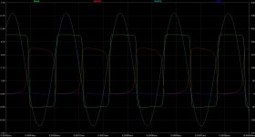
Pierce picogate
The attached picture shows the simulation of the Pierce oscillator at 11.2896 MHz using a pair of unbuffered '04. The first is used as the active device for the oscillator, the second as the squarer.
The circuit was simulated at 5V with the spice model of the 74HCU04, but could be used also at 3V3, with the 74LVCU04 or the Potato logic unbuffered inverter.
Green plot is the output of the squarer, red plot is the output of the oscillator, light blue plot is the input of the first gate, blue plot is the current flows in the crystal. The crystal dissipates around 350uW. The drive level can be decreased simply changing the value of a resistor.
The crystal load is around 17pF, as for the Laptech specs (16.5pF).
Attachments
The attached picture shows the simulation of the Pierce oscillator at 11.2896 MHz using a pair of unbuffered '04. The first is used as the active device for the oscillator, the second as the squarer....
*********************************
Very nice results Andrea.
These are exactly what that can be seen on an oscilloscope in a real circuit.
Keep up the good work, Gentlemen
The attached picture shows the simulation of the Pierce oscillator at 11.2896 MHz using a pair of unbuffered '04. The first is used as the active device for the oscillator, the second as the squarer.
The circuit was simulated at 5V with the spice model of the 74HCU04, but could be used also at 3V3, with the 74LVCU04 or the Potato logic unbuffered inverter.
Green plot is the output of the squarer, red plot is the output of the oscillator, light blue plot is the input of the first gate, blue plot is the current flows in the crystal. The crystal dissipates around 350uW. The drive level can be decreased simply changing the value of a resistor.
The crystal load is around 17pF, as for the Laptech specs (16.5pF).
************************************************
As mentioned earlier, although performance is wonderful due to the mechanism of the Pierce circuit, in this simplistic design - it wont be a match for the RutgerS Oscillator.
Cheers....
- Status
- Not open for further replies.
- Home
- Source & Line
- Digital Line Level
- The Well Tempered Master Clock - Building a low phase noise/jitter crystal oscillator