Sorry Anrea, I'm not impressed by the (often wrong) arguments of the gentlemen. And again: NO RESULTS!!!
Herbert,
take a look at this document (too big for attachment):
https://www.google.it/url?sa=t&rct=...bp55vMhcUNnPzMdsCk51qQ&bvm=bv.119745492,d.bGs
The Driscoll oscillator was built and measured (using a Nofech SC-Cut crystal), see page 103.
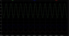
Waiting for the crystals, the following plot is the simulation of the Driscoll oscillator with the Laptech SC-Cut at 11.2896 MHz.
Green curve is the output from the collector of the bjt, the red curve is the voltage at the base of the bjt, the blue curve is the voltage across the crystal.
The loaded Q of the circuit should be better than 90% of the crystal Q, at least 720k with the Laptech crystal specified at a Q > 800k (usually the real crystals are better than the specs).
Emitter impedance is around 12 ohm, crystal ESR is around 110 ohm, that gives 90.2% of loaded Q.
The current in the crystal is around 0.85 mA, that gives a drive level around 79uW.
Attachments
Thanks Andrea! I have read the document quickly. For me there was nothing new.Herbert,
take a look at this document (too big for attachment):
https://www.google.it/url?sa=t&rct=...bp55vMhcUNnPzMdsCk51qQ&bvm=bv.119745492,d.bGs
The Driscoll oscillator was built and measured (using a Nofech SC-Cut crystal), see page 103.
One of the differences is that I use large AT-cut Xtals with tons of power into them, not the tiny ones as on the photograf in the document! Striking is that the published results with the Driscol are about the same as my results with the AT-cut Xtals!
Herbert.
I think we can have Andrea focus on developing the new oscillator and have it send to lab for test.
Herbert you may also develope your own for the community if you are interested in it.
I do really hope Andrea oscillator came out with good results, even don't, I wouldn't mind to pay all those as a kind of experiment.
Herbert you may also develope your own for the community if you are interested in it.
I do really hope Andrea oscillator came out with good results, even don't, I wouldn't mind to pay all those as a kind of experiment.
I think we can have Andrea focus on developing the new oscillator and have it send to lab for test.
Herbert you may also develope your own for the community if you are interested in it.
I developed my oscillator already many years ago!!
Read:
https://www.by-rutgers.nl/PDFiles/Reproducible Low Noise Oscillators.pdf
https://www.by-rutgers.nl/rutgerS-Clock.html
https://www.by-rutgers.nl/PDFiles/DC-receiver.pdf
and if you could read Dutch:
https://www.by-rutgers.nl/PDFiles/De Beste Oscillator.pdf
https://www.by-rutgers.nl/PDFiles/Beter Begrepen.pdf
https://www.by-rutgers.nl/PDFiles/De Beste Xtal-oscillator.pdf
Herbert.
Demian, Herbert, Alex, Jesper, and so on,
although hard to reach, we well know where we have to start to get low phase noise: the close in phase noise...
***************************************
Yes. My thoughts exactly.
The Rutgers oscillator presented at the start of this thread
provides (partially due to the extremely high drive level) and
good Laptech crystal, Phase Noise figures that are so superior to
anything in Audio today.
As mentoned earlier, I worked on Driscoll-type oscillator a few years back.
It is a different beast altogether since it oprates at close to series-resonance
as oppsed to the Rutgers oscillator that operates as a parallell-resonant circuit.
Each have their advantages, and disadvantages.
I recall the Driscoll (I used the original cicuit - you are using a simplified version) was very difficult to tame....a lot of spurious oscillations and frequency jumps even with carefully designed Bandstop dampers and resonance controll.
The Rutgers circuit (Colpitts type) on the other hand is VERY stable. This is a very important criteria for diy design.
The Driscoll provided much better PN measurements (but we never measured < 10 kHz from fc).
I recall reading some research docs a few years back where a comparison was made between
identical oscillator circuits, one equipped with AT- and the other with ST-cut crystals.
They were identical at f < 1kHz...with the ST being far superior at higher offset from the carrier.
I think Herbert mentioned something similar earlier...
@ fellow diy:ers here:
The Rutgers oscillator already has a very high performance for Audio.
If you build this one...dont worry about other designs....
Last edited:
Thank you Alexiss! This exactly the story.
My oscillator has not such low phase noise figures at frequencies >100 kHz from the carrier indeed.
Herbert.
My oscillator has not such low phase noise figures at frequencies >100 kHz from the carrier indeed.
Herbert.
I think we can have Andrea focus on developing the new oscillator and have it send to lab for test.
Herbert you may also develope your own for the community if you are interested in it.
I do really hope Andrea oscillator came out with good results, even don't, I wouldn't mind to pay all those as a kind of experiment.
One more time I have to punctualize the spirit of this thread.
As I stated in the first post, the first line, "I did start this thread to investigate the opportunity for a diyer to build a real low jitter oscillator".
This is not a commercial project. I'm doing this for the community, I have no commercial interest. The first batch I lost money.
In my honest opinion, this just means "diy audio".
Otherwise, there are tons of clock devices one can buy on the market (Crystek, Tentlabs, NDK, Pulsar, and so on).
Herbert's clock is just the TWTMC-C oscillator board. I have arranged the group buy from Laptech to get suitable crystals, that usually one cannot find on the shelf. The Laptech's crystals specs are known, I have published the measurement of each crystal of the first batch provided from Laptech. IMHO, they are very good AT-Cut crystals (high Q, cold welded package, polish finish).
Then, there was enough interest to get SC-Cut crystals, that usually have superior specs (higher Q). Again, I have arranged the group buy from Laptech, spending a lot of my little free time. Maybe I will loose money again.
The Clapp oscillator cannot work with SC-Cut crystals, since they have much higher ESR. So the jfet has not enough transconductance to overcome the losses due to the crystal resistance. Moreover, for the same reason, the Clapp oscillator does not work with 90/98 MHz 5th overtone AT-Cut crystals, just because they have around 40 ohm ESR.
The Driscoll oscillator seems to be more suitable for high ESR crystals, such SC-Cut type or 5th overtone AT-Cut type. In the first post I mentioned 3 oscillator circuits to investigate: the Clapp, the Driscoll and the Butler two emitters.
Now is the time of the Driscoll. I have already tested this oscillator with 90/98 MHz overtone Crystals, it starts correctly at the right frequency.
As soon as the SC-Cut crystals will arrive, I will test them with the Driscoll oscillator. If one would use them at high constant temp (82°C) the oven board is ready.
As I said several times I don't own the suitable gear to measure the phase noise. I can't afford a 100000 USD phase noise measurement system such as the Agilent E5052. This is an hobby for me, and I'm pleased to share my experience with diy audio community.
I have limited access to the above gear in a university lab. As I said in the first post, as soon as the 3 oscillators are ready, I will go to the lab to measure the phase noise.
Sincerely, I cannot do more than this.
BTW what is a TWTMC-C oscillator?One more time I have to punctualize the spirit of this thread.
Herbert's clock is just the TWTMC-C oscillator board. I have arranged the group buy from Laptech to get suitable crystals, that usually one cannot find on the shelf. .......................
The Clapp oscillator cannot work with SC-Cut crystals, since they have much higher ESR. So the jfet has not enough transconductance to overcome the losses due to the crystal resistance...... 40 ohm ESR. ...............
As I said several times I don't own the suitable gear to measure the phase noise.
................................
Sincerely, I cannot do more than this.
There are FETs which could overcome 40 ohm ESR, but I'm not interrested in SC-cut. The only thing I was interrested in is: good VCO's for my radio applications untill Guido (TentLabs) asked me to develop 'the best' clock oscillator for digital audio equipment. So I came up with a Clapp with extra AGC!! I published articles about the subject in different Radio Ham magazines and put the articles on my website so that any diyer could have it at his disposal. No more and no less, so Andrea and I coincide in many aspects.
BTW.: I also published my DC-receiver to measure the phase noise!
Herbert.
BTW what is a TWTMC-C oscillator?
The TWTMC-C is the Clapp oscillator board, see post #544.
............. One more time I have to punctualize the spirit of this thread.....
..........
.......
...
.
...Sincerely, I cannot do more than this.
*************************************
Andrea, your efforts, along with Herberts efforts are commended and VERY much
appreciated, at least by me.
There are, and there will be, various inevitable discussions (some good and some not)
on possible future permutations of the circuits presented here.
Hopefully you wont get discouraged by these ...
Once again:
I would like to point out that it is very difficult for the fellow
diy:ers to get their hands on descent clocks suitable for use in audio.
Audio-Product manufacturers (both large and small) promise the world, and deliver generic solutions.
It is my understanding that the Rutgers clock, equipped with the Laptech crystal, already
outperforms 99.99% of the Digital Audio clocks, available on the market.
This thread may very well be one of the only good sources of excellent info on digital-audio-related clocks.
So:
Keep up the good work, gentlemen.
Last edited:
*************************************
Andrea, your efforts, along with Herberts efforts are commended and VERY much
appreciated, at least by me.
Yes,extremely esteemed for me too.
Herbert,
What would you change in your rutgerS'Clock if the crystal frequency were to double or quadruple from 11MHz?
What would you change in your rutgerS'Clock if the crystal frequency were to double or quadruple from 11MHz?
The TWTMC-C is the Clapp oscillator board, see post #544.
Do you still have these boards? In case, send me 5 of them please.
Herbert.
Herbert,
What would you change in your rutgerS'Clock if the crystal frequency were to double or quadruple from 11MHz?
Look at eg. https://www.by-rutgers.nl/rutgerS-Clock.html in paragraph: Pictures. There you find the formula C' = C'' = 1000/fo with 4<fo<30 MHz, so C'=C''=100pF at 11.2... MHz and 50 pF with 22 and 24 MHz. That's all.
Herbert.
Last edited:
Do you still have these boards? In case, send me 5 of them please.
Herbert.
Herbert, you have PM.
#Pierce Oscillator#
Thank you Andrea for your informing us about the upcoming events.
I, for one, am looking forward to seeing the comparative measurements
of the three oscillators you plan on building.
I would like to add to the list (if possible) the grossly, and strangely understated Pierce Oscillator.
Working on a discrete version a while back, I was astonished by its remarkable
stability, ease of build, its desensitivity towards component variances, and
most importantly its PN measurements.
The final design used in the product was more complicated than the generic
schematics, however its performance was absolutely astonishing.
----------------------------------------------------------------
Please accept my apologies for this slight digressional note in you thread.
I hope it is ok with you.
Keep up the good work, gentlemen
Last edited:
#Pierce Oscillator#
....... Pierce Oscillator.
Working on a discrete version a while back, I was astonished by its remarkable
stability, ease of build, its desensitivity towards component variances, and
most importantly its PN measurements.
...................
During the last three decades I investigated nearly all fundamental circuits but the Clapp has won because of the great decoupling of the active components from the resonator and the possibility to incorporate the 'extra AGC' (with the BAT83) which is essential!
BTW what are the noise figures...??
Herbert.
#Pierce Oscillator#
I would like to add to the list (if possible) the grossly, and strangely understated Pierce Oscillator.
The Pierce is claimed to be the best oscillator for fundamental crystals, up to 20-25 MHz. I could add it to my list of testing, with my very very long time...
****************************************During the last three decades I investigated nearly all fundamental circuits but the Clapp has won because of the great decoupling of the active components from the resonator and the possibility to incorporate the 'extra AGC' (with the BAT83) which is essential!
BTW what are the noise figures...??
Herbert.
Hello Herbert.
I do not remember the exact noise figurs.
As you know, the design criteria in telecom are very different than Audio.
The design had conservatively biased resonator, since it was undesirable to have AGCs.
Cheers....
- Status
- Not open for further replies.
- Home
- Source & Line
- Digital Line Level
- The Well Tempered Master Clock - Building a low phase noise/jitter crystal oscillator