....he had been blamed !
I do beleive the parts selection and layout on the tda1541 square board is far to be optimum due to too much inductance due to the far caps. Also the simultaneous board is making too far added wires length after the fifo. I had the same issue with Ian I2S to Pcm board...it ads length and the mastering clocking slaving saves not all. Chance is these old pcm chip and speed are less sensitive to the jitter than nowadays delta sygmas.
Also I find all thes uka nichicon blue caps to be terrible sounding, despite in the audio range of Nichicons this is really one of the last part you want to see in your dac. Also some caps parts you do not want to see around the tda1541. I never liked personnaly the low DEM frequency with big capacitance values of the 14 DEM caps. It is liked by some because of the bad power supply of the three voltages and some things they didn't understand about its grounding with the chip due to the three voltage rails.
The last Aya5 despite I have not I know it is sim mode on the same board than the dac and has two ufl pads for clock injection (I asked it to Pedja Rogic...wanted vias for Andrea squarer but Pedja couldn't but offered gently the possibility of ufl pads to overpass the onboard Crysteq. All of this imo will drive your dac on the further level.
That said it is just constructive comment in order to push it even further. From what I see it is already a beautifull and awesome diy dac and work...congrats 🙂
Last edited:

D
Deleted member 537459
The ufl is 100mm long, maybe I can buy shortly but I don't think 2-3cm is a huge change.....he had been blamed !
I do beleive the parts selection and layout on the tda1541 square board is far to be optimum due to too much inductance due to the far caps. Also the simultaneous board is making too far added wires length after the fifo. I had the same issue with Ian I2S to Pcm board...it ads length and the mastering clocking slaving saves not all. Chance is these old pcm chip and speed are less sensitive to the jitter than nowadays delta sygmas.
Also I find all thes uka nichicon blue caps to be terrible sounding, despite in the audio range of Nichicons this is really one of the last part you want to see in your dac. Also some caps parts you do not want to see around the tda1541. I never liked personnaly the low DEM frequency with big capacitance values of the 14 DEM caps. It is liked by some because of the bad power supply of the three voltages and some things they didn't understand about its grounding with the chip due to the three voltage rails.
The last Aya5 despite I have not I know it is sim mode on the same board than the dac and has two ufl pads for clock injection (I asked it to Pedja Rogic...wanted vias for Andrea squarer but Pedja couldn't but offered gently the possibility of ufl pads to overpass the onboard Crysteq. All of this imo will drive your dac on the further level.
That said it is just constructive comment in order to push it even further. From what I see it is already a beautifull and awesome diy dac and work...congrats 🙂
you said the uka is not good... which one you prefer?
The delta sigma is so far from tda1541a...
And I try 9038pro dual mono in thrue sync.
Next step is feed also tda with +5-5+15 inductive shunt psu...
The ryanj supply use lt431 and lm317... no bad... Good result, but for best result i need another stuff...
I really think the tda needs linear SERIE regs for its 3 rails. Try pan Fr and Fc for the digital. Read some Aya2 audial blogs...
Last edited:
Fantastic, thank you for sharing @ilgavro . I have one question. I could not quite see the names of the additional Ufl connectors. I’m hoping that there is a way to run 2 dac boards in dual mono Configuration. This would require 2 sets of is2 .ufl headers which I think I see - can you confirm please?
I think it's possible although not 100%. I had a similar question:
https://www.diyaudio.com/community/...ffer-slaved-i2s-reclocker.348074/post-6237250
Greetings
Oli
https://www.diyaudio.com/community/...ffer-slaved-i2s-reclocker.348074/post-6237250
Greetings
Oli
D
Deleted member 537459
Yes, you can use 2 tda1541a, next step a try it, is arrive this week the material for the second chipFantastic, thank you for sharing @ilgavro . I have one question. I could not quite see the names of the additional Ufl connectors. I’m hoping that there is a way to run 2 dac boards in dual mono Configuration. This would require 2 sets of is2 .ufl headers which I think I see - can you confirm please?
This looks very interesting @ilgavro!
I also use the boards from ryanj but in balanced PCM mode and with sowter opt.
it is fed with Ians fifopi q3 and the excellent 5 and 6 mhz clocks from Andrea (They are the best upgrade one can get for digital!)
I am very interested in his fifo board.
@diyiggy I am very fond of my current dac, you mentioned some flaws that I also though would be worth to change/improve but I started out with the standard build and it is so good that it is running 5months now without the urge to change it.
Last week my Aya5 board arrived, soon I will be comparing it with the @ryanj boards.
regards,
Attachments

That is interesting Supersurfer. Have you the AT cut or the last big SC cut ? I'm looking forward to read your review with the Crystek VS the squarer injection frol the SC cut if you have those last design. I still have to finish my SC cut last version. 5 Mhz and have also 5 Mhz AT and 22/24 mhz.
Had you a chance to benchmark the discrete aya5 vs aya2 or 4 with the power suply mods on the -15V ?
I really have no clue of the Aya5 despite exchanging with Pedja before aand during the poll. The new power supply transistors and the renewed analog power supply seems different. Feel free to use my pm if you think it is too much off topic there 🙂
I am glad Pedja used the sep polymer instead the sepc as some did. But I really think it is better without andjust the smd on the -15V.
Saw the pictures...so last SC cut design 🙂....oups no room on the aya5 board for the big diamer excellent FC cap of the Aya2 threads...too bad !
Last edited:
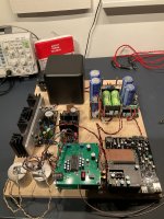
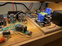
Ilgavro thank for the photos and the report, it's fun
Coaxial cables welded on FIFO also a small loss😉
Coaxial cables welded on FIFO also a small loss😉
Hello,
I remember asking some months ago about using coaxial cables and proper termination. I was told that a " proper match" of impedance/ cable/ connector/ circuit isn't that critical in " our situation ". . Just soldering the cable directly to the circuit would not be a cardinal sin.
Making the connection between Fifo and dddac using Dupont connectors on both sides and a kind of flat cable.
Don't know if these u.fl cables including these microscopic connectors will give better sound.
What i do know that using cables/ connectors you will usually see in computers is much easier and reliable. If an overweight mosquito at full speed hits an u.fl cable you will likely miss some bits.
Greetings,Eduard
What is nice is they are individually grounded... 🙂...some says it matters, some others say it doesn't...
I came late here.
Andrea_mori threads are so interesting.
Are there as my possibility to buy his board?
Andrea_mori threads are so interesting.
Are there as my possibility to buy his board?
Andrea confirms this functionality here: #28I think it's possible although not 100%. I had a similar question:
https://www.diyaudio.com/community/...ffer-slaved-i2s-reclocker.348074/post-6237250
Greetings
Oli
Hi Eduard,Hello,
I remember asking some months ago about using coaxial cables and proper termination. I was told that a " proper match" of impedance/ cable/ connector/ circuit isn't that critical in " our situation ". . Just soldering the cable directly to the circuit would not be a cardinal sin.
Making the connection between Fifo and dddac using Dupont connectors on both sides and a kind of flat cable.
Don't know if these u.fl cables including these microscopic connectors will give better sound.
What i do know that using cables/ connectors you will usually see in computers is much easier and reliable. If an overweight mosquito at full speed hits an u.fl cable you will likely miss some bits.
Greetings,Eduard
ufl connectors are a pain for DIYers (in my opinion) as they are fragile and aren't designed for experimentation (read constant swapping out of connections) but they are (again, in my opinion) leagues ahead of using ribbon connectors. Over the years, I've tried loads of things and with the exception of a good SMA header connection ufls are a great sounding connection. Use cables as short as possible and with as big a diameter as possible. These are generally inflexible and a pain to wire but will sound better!
I've tried soldering the wires to the boards and this is perfectly acceptable but really fiddly. Before Ian Canada's multi-channel Fifo board came out I had to split the single ufl output and I did it but what a pain! I change boards around quite a lot during periods of experimentation and the ufl connectors start to wear...I've resorted to hot glue at some points to get them to stick!
Hope this helps,
Crom
You can buy his designs through his own website: https://www.thewellaudio.com/I came late here.
Andrea_mori threads are so interesting.
Are there as my possibility to buy his board?
Hello,
At Mouser i bought the Hirose tool made to disconnect the plug from the board. It will allow to pull the plug exactly at the right angle from the plug. A plier tool will apply to much force on the connector because if you need some strength to pull the plug you will almost automatically use a tighter grip on the connector.
Even connecting the plug needs good eyesight and applying downforce with something similar to a matchstick. Especially if you cannot reach the connecting area properly it is not that easy.
A lot of folks here will connect and disconnect things several times a year. If they disconnect when your holding your gear upside down the cable has to be changed for sure!!. If you are poking around with a big tool inside your chassis hitting these tiny u.fl cables could cause problems. I wonder if they still sound better if the connecting they are making is not close to perfect.
These coaxial cables going from Sinepi to Andrea's clock circuitry are even worse. The cable is to rigid . If there is not much room it is already difficult to position the plug in the right spot before entering the terminal. On the Sinepi the terminal are close to each other which doesnt help. I managed to '' disintegrate 'the terminal on the Sinepi because at one moment there was an '' overload '' on the connection. Then i decided to use a staight terminal because my cable already has a 90 degrees angle.
The u.fl cable between fifo and DDDAC is 6 inches which should function properly. I can understand short cable runs are better. BUT if 6 inches is not short enough i will go for another circuit. I got 3 extra cables from Ian but i am not planning to disconnect things once they are working. Maybe a heatshrink fixing the 3 cables together close to the terminal can be good
Greetings, Eduard
P.s i wonder how people here disconnect the u.fl cables?
The proper tool sounds good.
I use a good pair of angle nose tweezers and slide the points under the connector with a point on each side. Then gently prey it up using the lever of the tweezer to pry it straight up.

When the connector becomes lose, the sound degrades. The 4 little semi circles that clamp onto the ring of the connector get wider with use. I have been able to resurrect them by carefully squeezing them back together with pilers.
I use a good pair of angle nose tweezers and slide the points under the connector with a point on each side. Then gently prey it up using the lever of the tweezer to pry it straight up.
When the connector becomes lose, the sound degrades. The 4 little semi circles that clamp onto the ring of the connector get wider with use. I have been able to resurrect them by carefully squeezing them back together with pilers.
To disconnect the u.fl cable I just put a small flat screwdriver under the cable end and jig upwards; it will come off pretty straight without damaging the connector.
- Home
- Source & Line
- Digital Line Level
- The Well synchronized asynchronous FIFO buffer - Slaved I2S reclocker