Correct blitz. That works perfectly and keeps the clocks powered on what helps sound quality. I use a cheap cc cv to charge In between
Better SQ. I use it for my dac ps, clock ps but also in my field coil ps. It is really remarkable that the rectifier in a field coil ps is so clearly audible; we are talking about energizing an electromagnet of a loudspeaker so nothing in direct sound path but it just makes more music everywhere I use it.Hi Supersurfer,
How would you subscribe the advantages from the Saligny. Less heat, better SQ,...... Have you experienced with this component in (pre-) amplifiers or tube-amplifiers. Would you recommend it?
I have used supercaps a lot and have found they have a sweet spot for digital sources so I use it in my streamer but not on my dac, I do not like the sound on the analog ps part.Supersurfer,
a few more questions: are you using supercaps with the clock or is it Vref on your DAC? Have you tried Andrea's TWRPS-pp/ugl? If so, what were your impressions on them and generally on supercaps wherever you have applied them?
I would really like to try batteries + supercap like DDDAC (thanks for your reply by the way!), but it seems complicated and quite more expensive Reading his blog it seems the benefits are there, but marginal. I also have a HTPS7000 which could help a little with the non-battery solution.
using supercaps on the drixo would need a series caps for 15v and it is a lot to build for a small increase in quality, I tried with Ians battery board and supercaps in parallel.
Hello Blitz,
For the clocks i use the same Eaton Doede is using but i dont use any batteries.
I asked Doede to make a reduced dimensions model of his regulated power supply because i wont use the rectifier and caps ( pre regulator part) . It allows me to fit the circuit board a lot more easily closer to the load.
With a separate heatsink you can use it for a Roon nucleus or other items that require more current.
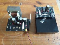
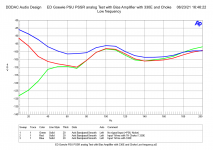
In the last attachment you can see the benefit of using a choke instead of the 330E resistor ( this was described in Doede's blog )
In the third attachment you can see the circuitboard and its power output cable as used for the Roon nucleus.
The second photo shows Doede's board to take care of the switching between the Asian charger and Doede's regulator with LC preregulation. Doede explained somewhere on this site or his own site how the big board is working. IF the batterie or batterie/supercap combo drops below a certain voltage it needs to be recharged and this can only be done by something like the Asian unit.
Of course if the load is small the voltage should not drop a lot but if you are absent for a few days voltage will drop and then the little Doede board will see the batterie/supercap as a big short circuit. And on top of that it is not constructed to be used as a charger.
I have used BIG batteries for a class D amp in my home cinemaset. Last time i needed to replace the pair of batteries that supply 24 volts ( single rail) i decided to go back to choke input because Lundahl started selling a big choke that could do this job perfectly. Like some people on this site i believe that for certain circuits there is nothing wrong with a BIG choke input power supply.
Using batteries will of course isolate the circuit from the rest of your gear.
BUT i wonder how many diy digital circuits builds published here could be improved by '' simply '' reducing mutual interference between the big number of circuit boards. IF boards are designed to be used like a pile of boards it could be OK if the designer knows what he is doing but i can imagine attaching loads of boards from different designers on a piece of wood will not work perfectly. It could sound better than your latest baby ( partly also because you expect it to be better!).
I remember reading about ( my?) class D amp interfering/altering the image of a nearby TVset. Could one compare class D gear in with digital gear in this respect?
Greetings, eduard
For the clocks i use the same Eaton Doede is using but i dont use any batteries.
I asked Doede to make a reduced dimensions model of his regulated power supply because i wont use the rectifier and caps ( pre regulator part) . It allows me to fit the circuit board a lot more easily closer to the load.
With a separate heatsink you can use it for a Roon nucleus or other items that require more current.
In the last attachment you can see the benefit of using a choke instead of the 330E resistor ( this was described in Doede's blog )
In the third attachment you can see the circuitboard and its power output cable as used for the Roon nucleus.
The second photo shows Doede's board to take care of the switching between the Asian charger and Doede's regulator with LC preregulation. Doede explained somewhere on this site or his own site how the big board is working. IF the batterie or batterie/supercap combo drops below a certain voltage it needs to be recharged and this can only be done by something like the Asian unit.
Of course if the load is small the voltage should not drop a lot but if you are absent for a few days voltage will drop and then the little Doede board will see the batterie/supercap as a big short circuit. And on top of that it is not constructed to be used as a charger.
I have used BIG batteries for a class D amp in my home cinemaset. Last time i needed to replace the pair of batteries that supply 24 volts ( single rail) i decided to go back to choke input because Lundahl started selling a big choke that could do this job perfectly. Like some people on this site i believe that for certain circuits there is nothing wrong with a BIG choke input power supply.
Using batteries will of course isolate the circuit from the rest of your gear.
BUT i wonder how many diy digital circuits builds published here could be improved by '' simply '' reducing mutual interference between the big number of circuit boards. IF boards are designed to be used like a pile of boards it could be OK if the designer knows what he is doing but i can imagine attaching loads of boards from different designers on a piece of wood will not work perfectly. It could sound better than your latest baby ( partly also because you expect it to be better!).
I remember reading about ( my?) class D amp interfering/altering the image of a nearby TVset. Could one compare class D gear in with digital gear in this respect?
Greetings, eduard
Attachments

Thats nice...have you ever tried to use this 61F bank for powering the clock in "pure" mode as Ian would say, so no battery/PSU attached ? I gues for some time it should have stored enough current...no ?
I will experiment a bit with the supercapacitors and see what they do...
I love Doede's idea to program an Aduino to control relais etc...
IF the supercap-solution is sonically the way to go, it might be the choice as well for Andrea's FIFO/DAC...which than will need more tails to be controlled. A small 10Euro CC/CV-Board 5A per rail would do the job...with a larger high current voltage source for charging which I could share to charge the Ultracaps.
Ian has build sucha solultion , but 125 Euro per rail is a bit too much...alone fot the charger...plus 300 Euro for the 500F packs in 18V...
Hello ,
Doede is using a combo of batterie and supercap so the amount of energy stored is bigger.
Some time ago i read about a public transport by bus that runs on supercaps that were charged at every stop the bus made.
If the load does not ask for a lot of current it could be done i guess. This way the sound quality would drop once an hour? for a few minutes to recharge the supercap again. But if your digital system is switched on 24/7 it could diminish the lifetime of the supercap?
If the circuit does not a voltage in a order of 3 to 5 volt it will much easier to make a lot of F which is needed when there is a serious current need by the load.
So far my set up is not working and i kind of stopped looking for the culprit so to say.
Of course there are to many boards if you are using the Canadian solution And i cursed a lot with the garden hose output cable needed for the Sinepi circuitboard.
Greetings, eduard
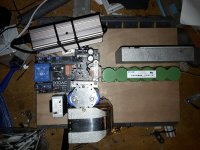
P.s in the attachment my Italian clocks with its power supply
Doede is using a combo of batterie and supercap so the amount of energy stored is bigger.
Some time ago i read about a public transport by bus that runs on supercaps that were charged at every stop the bus made.
If the load does not ask for a lot of current it could be done i guess. This way the sound quality would drop once an hour? for a few minutes to recharge the supercap again. But if your digital system is switched on 24/7 it could diminish the lifetime of the supercap?
If the circuit does not a voltage in a order of 3 to 5 volt it will much easier to make a lot of F which is needed when there is a serious current need by the load.
So far my set up is not working and i kind of stopped looking for the culprit so to say.
Of course there are to many boards if you are using the Canadian solution And i cursed a lot with the garden hose output cable needed for the Sinepi circuitboard.
Greetings, eduard
P.s in the attachment my Italian clocks with its power supply
Attachments
All I can find in this 31-page thread are pictures and User Manuals.
Were the schematics for any/all of the andrea_mori offerings in this thread ever shared (publicly)?
I'm specifically looking for the basic I2S/MCK line-in / line out schema. Not necessarily the HDMI or RPI.
Or maybe someone has a better (schematic) idea of what this DIYinHK fifo/i2s device is? That is, which specific logic chips and the schematic showing the connections.
https://www.diyinhk.com/shop/audio-kits/165-fifo-reclock-jitter-eliminator-for-8-channel-dac.html
Thanks!
Last edited:
I'm going to assume the design of the andrea_mori offerings are beyond the std. 74HC74-flip-flop-based re-clocker (using good, clean power).Were the schematics ...
@philipsmarantz: Hi ...
Yes, that is my impression. Andrea Mori has aimed to create solutions that have the lowest possible phase noise using the ICs that perform best in this respect. And, no, to my knowledge the actual schematics have never been shared here or elsewhere but his solutions are available from his website (i.e. an inverter, the FiFo, DAC etc. ... thewellaudio.com )
My guess is that Andrea's solutions perform on a somewhat higher level than e.g. the diyinhk devices (no offense, but my guess).
Cheers,
Jesper
I'm going to assume the design of the andrea_mori offerings are beyond the std. 74HC74-flip-flop-based re-clocker (using good, clean power).
Yes, that is my impression. Andrea Mori has aimed to create solutions that have the lowest possible phase noise using the ICs that perform best in this respect. And, no, to my knowledge the actual schematics have never been shared here or elsewhere but his solutions are available from his website (i.e. an inverter, the FiFo, DAC etc. ... thewellaudio.com )
My guess is that Andrea's solutions perform on a somewhat higher level than e.g. the diyinhk devices (no offense, but my guess).
Cheers,
Jesper
If one is going to post a project in the main DIYA forum, even one with commercial interests in mind, then a full schematic is mandatory. Otherwise, the Marketplace sub-forum should be obligatory.And, no, to my knowledge the actual schematics have never been shared here or elsewhere but his solutions are available from his website (i.e. an inverter, the FiFo, DAC etc. ... thewellaudio.com )
Some of us are Veroboard-only diyers.
Well, I am not sure is this is my definition of DIY.
Many producers give us ready to use boards to build our DAC or amp. Soekris, twisted pear, Waveio many...They give us thechoice to build the psu, the output stage, the enclosure around it and often even support mods to the boards...for the brave ones. So, there is a lot Diy involved still. None has published their schematics etc as this would immediately result in cheap chinese copies as there is no respect for intellectual property.
When you now compare the results to commercial products...well...what a nice offer, we talk now about DCS and above quality for everyone affordable who can solder....Soekris has great Fifo/Dacs, i got the dam1941, but Andreas stuff is beyond that...another league.
So, even when someone offer this as a complete board...i doubt the objective is to become rich...its a favoir to the community.

I am pretty sure Andrea is not into it to earn a lot of money. If he would, he would have made much more exposure for his products, keep enough stock to sell and get a distributer like Ian.
He is doing this for the love of audio and music and the small amount he earns with selling his designs is to have a bit of compensation for all the development costs he is making.
His drixo clocks are real SOTA designs and nothing beats them. His daclite is also a very good design and can keep up with the likes of dCS.
I am doing some slow progress on the Super-Cap-Front...this thing will take much more time to make a fair conclusion I guess.
The reason: When I switch from one PSU to the other, there is a short amount of time where the clock does not get any power. You can see the LED flickering when swiching ( I used a manual switch originally). So, I tried to make the switching faster and build a relais switch with a remote control...but even that is degrading the sound quality. The more often you switch, the worse the sound becomes towards metalllic, hard.
So, I guess...a direct A/B comparison is not possible, instead a long-term listening is the only way to see which solution gives most satisfiying results.
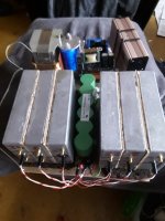
The cheap 40 Euro 83F/16V Supercap bank from Amazon works nicely with 10 Euro CC/CV-board and another 10 Euro relais board which measures automatically the voltage of the super-cap and if it goes down below the theathold level of 12V, thecharger gets connected to charge to 16V and after that disconnects itself again.
So, this is a 20 Euro "UCpure" solution which is scalable vs. the 125 Euro for the original board...plus I can choose higher / faster charging current (than 3A in Ucpure) and I can select any voltage I want.
The reason: When I switch from one PSU to the other, there is a short amount of time where the clock does not get any power. You can see the LED flickering when swiching ( I used a manual switch originally). So, I tried to make the switching faster and build a relais switch with a remote control...but even that is degrading the sound quality. The more often you switch, the worse the sound becomes towards metalllic, hard.
So, I guess...a direct A/B comparison is not possible, instead a long-term listening is the only way to see which solution gives most satisfiying results.
The cheap 40 Euro 83F/16V Supercap bank from Amazon works nicely with 10 Euro CC/CV-board and another 10 Euro relais board which measures automatically the voltage of the super-cap and if it goes down below the theathold level of 12V, thecharger gets connected to charge to 16V and after that disconnects itself again.
So, this is a 20 Euro "UCpure" solution which is scalable vs. the 125 Euro for the original board...plus I can choose higher / faster charging current (than 3A in Ucpure) and I can select any voltage I want.
Last edited:
Hello,So, I guess...a direct A/B comparison is not possible, instead a long-term listening is the only way to see which solution gives most satisfying results
If the difference between two things can only be heard when you can switch between the two within a second i would not worry at all.
You should go outside the room and ask someone else to switch or not switch to the other one. When you return after TEN minutes you should be able to tell if someone did make a change.
Very simple to me.
If you have to keep switching you are a true audiophile.
Greetings, eduard
Hello everyone. I was reluctant to post anything because I felt I wasn't ready, but I have a bit more meat on my bones and wish to share. I was initially very confused about the noise which Andrea as well as @Blitz was talking about, but my mind is clearer on the matter now.
Andrea talked about the RPI platform being noisy and should be keep far away from the DAC. I think I know why. The RPI has RF noise due to being WiFi capable ... if this had only been mentioned earlier the confusion would have been far less.

This will probably mess with the clocks so yes. An RPI with WiFi onboard is a bad idea. Basically, the Pi unit MUST be RF shielded. As long as there is no RF transmitted or received in close proximity to the DAC/Clocks - outside or inside a project box - a PI streamer can live very close to the DAC/Clocks. If there is RF noise, be that from a WiFi source or a PSU itself, then yes, there are issues. So obviously this needs to be taken care of.
I know Blitz have a thread called Path to noiseless Linux streamer... which I will go over - his findings might mean a world of difference, or not, that is what I will find out by reading, but in the meantime there is something.
Assume we have taken care of the RF issues, if we then look at the noise levels from the Pi2AES and the Holo Audio Red, they are really good, meaning low and shouldn't pose much issues for the FiFo or DAC. These are "dum boxes" meaning the OS and media player is a sub topic of which is better, but the hardware is not the issue here, at least in my opinion.
https://goldensound.audio/2023/02/09/holo-red-streamer-ddc-measurements/
https://goldensound.audio/2021/07/22/pi2aes-streamer-measurements-and-5v-psu-mod-instructions/
Link to a HOLO Audio Red review and mentioning of the RF issue: https://www.superbestaudiofriends.org/index.php?threads/holo-audio-red.13128/#post-401522
Andrea talked about the RPI platform being noisy and should be keep far away from the DAC. I think I know why. The RPI has RF noise due to being WiFi capable ... if this had only been mentioned earlier the confusion would have been far less.
This will probably mess with the clocks so yes. An RPI with WiFi onboard is a bad idea. Basically, the Pi unit MUST be RF shielded. As long as there is no RF transmitted or received in close proximity to the DAC/Clocks - outside or inside a project box - a PI streamer can live very close to the DAC/Clocks. If there is RF noise, be that from a WiFi source or a PSU itself, then yes, there are issues. So obviously this needs to be taken care of.
I know Blitz have a thread called Path to noiseless Linux streamer... which I will go over - his findings might mean a world of difference, or not, that is what I will find out by reading, but in the meantime there is something.
Assume we have taken care of the RF issues, if we then look at the noise levels from the Pi2AES and the Holo Audio Red, they are really good, meaning low and shouldn't pose much issues for the FiFo or DAC. These are "dum boxes" meaning the OS and media player is a sub topic of which is better, but the hardware is not the issue here, at least in my opinion.
https://goldensound.audio/2023/02/09/holo-red-streamer-ddc-measurements/
https://goldensound.audio/2021/07/22/pi2aes-streamer-measurements-and-5v-psu-mod-instructions/
Link to a HOLO Audio Red review and mentioning of the RF issue: https://www.superbestaudiofriends.org/index.php?threads/holo-audio-red.13128/#post-401522
That's not the only reason. Its a computer, would be more to the point. There is lots of digital noise being generated. Some of the noise is on the ground, some on the power, and some of it is radiated out into space....The RPI has RF noise due to being WiFi capable ...
It is suggested to study the book, "Electromagnetic Compatibility Engineering," by Henry Ott. Its quite practical and full of useful information. Its not one of those books that requires a lot of math to get anything out of it.
Last edited:
My preference is to use asynchronous USB. However, it requires a lot of care to keep the EMI/RFI out of the dac. Problem is we need a device to store digital files and send them to the dac. A slow, low power, well isolated computer is likely to be easier to deal with than a computer that is very fast and powerful.
- Home
- Source & Line
- Digital Line Level
- The Well synchronized asynchronous FIFO buffer - Slaved I2S reclocker