Have used, this protection in SARA amplifier with success 🙂
PCB attached 😉
Regards ,Alex
And I have used it in my Telos Clone without any problems. Works really well.🙂
I thought the question was about (current) overload....😉
Fab
Sorry you are probably right...😱
And I have used it in my Telos Clone without any problems. Works really well.🙂
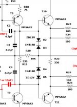
Look closely where Alex MM connected his sensing circuit. It's on the amplifier side of the speaker relay.
that is where the circuit senses output. It feeds into the 22k and the 20k.The big red arrow would be the correct place to sense from. That's not what the schematic is showing though.
The output on the comparitor will be a pn junction from ground at low state so the base of the relay transistor will have some voltage present. The 10k resistor turns it off.
When the comparator output goes Lo, the switching transistor has only the 5k6 pull up resistor. The series combination of 5k6 and 27k can only supply ~0.4mA to the base||10k
The 10k will draw ~0.05mA and that still leaves ~0.35mA entering the base.
I don't see that adding the 10k has done much.
If they had used a 3k base resistor and a 10k pull up, then this would probably work better as a switch to turn on the relay.
But I would still prefer a driver transistor between the comparator and the switching transistor.
Last edited:
I agree with the driver transistor. A diode in series with the existing driver transistor emitter would probably allow for removal of the 10k resistor completely.that is where the circuit senses output. It feeds into the 22k and the 20k.
When the comparator output goes Lo, the switching transistor has only the 5k6 pull up resistor. The series combination of 5k6 and 27k can only supply ~0.4mA to the base||10k
The 10k will draw ~0.05mA and that still leaves ~0.35mA entering the base.
I don't see that adding the 10k has done much.
If they had used a 3k base resistor and a 10k pull up, then this would probably work better as a switch to turn on the relay.
But I would still prefer a driver transistor between the comparator and the switching transistor.
The output of the comparator will likely be around 0.6V at low state (might be higher, I'm not that familiar with the device). The base of the driver transistor will likely be conducting at that. The 27k resistor and the 10k resistor form a voltage divider bringing the voltage at the base to slightly over 1/3 the output voltage of the comparator output, turning the transistor off.
Hi all,
It's 2017 now, I collected some materials and plan to make it wiki-like. Here's the new build thread.
http://www.diyaudio.com/forums/solid-state/304699-goldmund-wiki-build-2017-a.html
best,
Eric
It's 2017 now, I collected some materials and plan to make it wiki-like. Here's the new build thread.
http://www.diyaudio.com/forums/solid-state/304699-goldmund-wiki-build-2017-a.html
best,
Eric
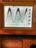
Hi ! In this amplifier I built I am having some trouble.
1. parasitic oscillation at middle level input signal ( 400 mV ) measured at the output with 8 Ohms resistive load. No oscillation at maximum power before clipping nor minimum power. It tends to improve when increasing gate resistors to aprox 820 Ohms, but output power is reduced also.
2. inverted T5 ?
3. low quiescent current. Measured placing a 0.1 Ohm resistor in place of one of the fuses, showed 20 mA. I increased the current by placing a trimpot at 435 Ohms instead of R19. I adjusted current to 340 mA total. Is this correct ?
4. output inductor made over specified 0.22 Ohms resistor. Most amplifiers use 10 Ohms for that resistor. Is this OK ?
5. changed C2 to 47 pF and its symmetrical on T8 and T9 , the oscillation is better but raise time is worse now from 1us to 2.5us - How to eliminate this oscillation ? I am trying not to add extra capacitors to de input stage ...
Help and advice much appreciated.
Attachments

without simulating your circuit I would suggest omitting both Miller capacitors (the 4.7pF you have suggested might be increased to 10pF) but add a 100pF+100 ohm series pair between the collector of T8 and ground. I would also add a 10nF across R22.
However I wonder if the VAS currents will be high enough. What is the voltage across R17?
What is the frequency of the oscillation?
However I wonder if the VAS currents will be high enough. What is the voltage across R17?
What is the frequency of the oscillation?
Hello john_ellis, thank you for your reply. Problem solved, please check this link
Goldmund Mods, Improvements, Stability
Kind regards
Roberto
Goldmund Mods, Improvements, Stability
Kind regards
Roberto
POWER SUPPLY VOLTAGE DROP & NOISE AT THE OUTPUT
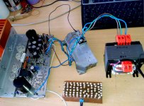
My Goldmund clone (4 output MOSFET version) is working. Except for 2 issues:
Issue #1: the power supply shows a huge drop from +/- 56V rails (no input signal) to +/-50V when full power before clipping. Measured at the speaker output, clipping appears at 42V amplitude over 8 Ohm resistive load.
The transformer is rated 330 VA and was custom ordered, it shows the specified 40 VAC + 40 VAC even at full power. Measured with a True RMS multimeter. Please see the attached picture with the complicated wave shape as input to the rectifier bridge, 20V/division scope scale.
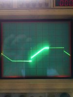
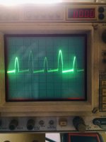
Issue #2: with the input shorted, the second attached waveform appears at the speaker output, with resistive 8 Ohm load. The amplitude is about 10 mV peak to peak, 5 mV/division scope.
There is no significant votage drop in the cables. I don't think that the rectifier bridge can produce such a voltage drop. This is a KBPC5010 ( 1000V - 50A) (click for PDF)
This board has 2 x 10000 uF Panasonic good quality electrolytic capacitors, one on each 56V DC rail.
What about the rails voltage drop ? Is this noise normal ? How can I fix both issues ?
Thank you
My Goldmund clone (4 output MOSFET version) is working. Except for 2 issues:
Issue #1: the power supply shows a huge drop from +/- 56V rails (no input signal) to +/-50V when full power before clipping. Measured at the speaker output, clipping appears at 42V amplitude over 8 Ohm resistive load.
The transformer is rated 330 VA and was custom ordered, it shows the specified 40 VAC + 40 VAC even at full power. Measured with a True RMS multimeter. Please see the attached picture with the complicated wave shape as input to the rectifier bridge, 20V/division scope scale.
Issue #2: with the input shorted, the second attached waveform appears at the speaker output, with resistive 8 Ohm load. The amplitude is about 10 mV peak to peak, 5 mV/division scope.
There is no significant votage drop in the cables. I don't think that the rectifier bridge can produce such a voltage drop. This is a KBPC5010 ( 1000V - 50A) (click for PDF)
This board has 2 x 10000 uF Panasonic good quality electrolytic capacitors, one on each 56V DC rail.
What about the rails voltage drop ? Is this noise normal ? How can I fix both issues ?
Thank you
Attachments
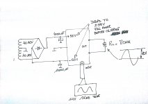
Drop on the bridge is about 1V per rail, rest is drop in transformer, more capacitance can help also.
You measure 40Vac but thats not sinusoidal voltage, it is like clipped sinus. Put scope on rail (AC) and see what is there, you can also measure transformer secondary.
Issue #2, spikes coming from rectifier, it is EMI coupling to input wires.
You can damp that spike with snubber on trafo secondary.
That trapezoidal wave form I am not sure from where coming.
Thank you radule, the trapezoid waveform is what I see at the AC applied to the bridge, meaning the 80 VAC directly coming coming from the trafo. I had 0.1 uF capacitors across the 4 diodes of the rectifier bridge, but the signal showed some ringing. If you take a close look, a thin spike can be seen I think when the diodes reverse.
So, as you said, or the transformer is not enough or the problem is that it need more filtering. Do you think that 15000uF or 20000uF would be OK ?
So, as you said, or the transformer is not enough or the problem is that it need more filtering. Do you think that 15000uF or 20000uF would be OK ?
You already have cap multiplier at voltage gain stages, so 10000uF could be enough for 8 ohm loads. For lower load impedance you can consider more capacitance.
If you are satisfied with sound, dont touch anything 🙂
If you are satisfied with sound, dont touch anything 🙂
I think that the power supply is simply collapsing because the transformer is rated 160 VA, and this should happen while listening music. So I will follow your advice and leave it as it is.
Issue #2: the input is shorted. How is it possible for EMI coming from the power supply transformer to produce this output noise. I can also see that is located in the positive region. No negative excursion of the signal (below ground). Any ideas about this filter you propose ? How would you do it ?
Issue #2: the input is shorted. How is it possible for EMI coming from the power supply transformer to produce this output noise. I can also see that is located in the positive region. No negative excursion of the signal (below ground). Any ideas about this filter you propose ? How would you do it ?
Dear sajti, thank you.
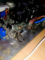
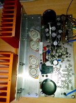
Here are the pictures, this is the well known 4 MOSFET original version with the Nagys boards I bought from him.
Please notice that this noise appears with the input shorted, and 8 Ohm resistive load. There is no cable attached to the input. Just the shorted terminals. It has 20 mV and it is measured at the speaker output. Matches the picture from my previous posts.
I would like to eliminate it.
Attachments

Issue #2: the input is shorted. How is it possible for EMI coming from the power supply transformer to produce this output noise. I can also see that is located in the positive region. No negative excursion of the signal (below ground). Any ideas about this filter you propose ? How would you do it ?
Huh,.....
my coment was related to issue number and picture number, but now I think
that you swapped pictures.
Is this pictures attached below, what you measured on amplifier output?
If it is, then forget about my coment on EMI coupling.
That on the picture is charging pulses of main electrolitic capacitors.
If you really have that on the output, you will hear buz and hum, but you already mention that amp is silent.
So it could be measuring error, gnd probe of the scope attached on the high current path, or ground loop....
Attachments

No radule, there is no picture swapping. If you read my first original question on this subject I am showing the speaker output. I am measuring with a good old Tektronix 465 because mi other digital Tektronix is useless for this low level signals. The power supply drop issue I figured out myself and it is no longer a problem.
The noise seen at the output ...mmm...this worries me. The scope is placed with ground lead at the very point where all grounds (single point) are connected, meaning the 0V from the power supply and ALSO the speaker ground. The scope's ground cable doesn't seem to be picking up noise, I shrinked it with my hand and the signal remains the same. The probe is a brand new B&K Precision 100MHz.
Any ideas ?
- Home
- Amplifiers
- Solid State
- The Very Best Amplifier I Have Ever Heard!!!!