Hallo meanman.
Have you finished a build with this boards?
Impressions- PM- or here can be helpful for better orientation.
Comparing to other- newer- Amps, done here in Forum, since 2015- with more
modern ideas- revisiting some old stuff.
Cheers Bangla.
Have you finished a build with this boards?
Impressions- PM- or here can be helpful for better orientation.
Comparing to other- newer- Amps, done here in Forum, since 2015- with more
modern ideas- revisiting some old stuff.
Cheers Bangla.
Bangla
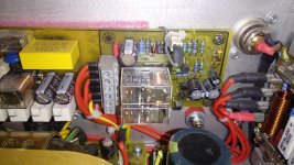
Not finished yet but completely soldered.
Tweaked some resistor values strenght of the Telos clone are the vocals and soundstage regarding Pinochico
Not finished yet but completely soldered.
Tweaked some resistor values strenght of the Telos clone are the vocals and soundstage regarding Pinochico

Bangla
Not finished yet but completely soldered.
Tweaked some resistor values strenght of the Telos clone are the vocals and soundstage regarding Pinochico
It's pinnochio
Good day to all!
Prompt how to adjust the mix of DC offset? I have a DC offset voltage of 0,9V at the front end of +/- 77B (R32, R33 = 2 k).
R8 unscrewed to the left engine. Not enough stroke adjustment.
But at a voltage of +/- 65V front end (R32, R33 - 2.7k), DC offset is +/- 20mV.
Thanks in advance.
Prompt how to adjust the mix of DC offset? I have a DC offset voltage of 0,9V at the front end of +/- 77B (R32, R33 = 2 k).
R8 unscrewed to the left engine. Not enough stroke adjustment.
But at a voltage of +/- 65V front end (R32, R33 - 2.7k), DC offset is +/- 20mV.
Thanks in advance.
Guyz, what kind the protection is used in goldmund.
I mean overload protection, there is no protection of it, only Fuse?
I mean overload protection, there is no protection of it, only Fuse?
Guyz, what kind the protection is used in goldmund.
I mean overload protection, there is no protection of it, only Fuse?
Overload "protection" is provided by Zener/signal diodes in series limiting the gate voltage of mosfet thus output current.
The Fuses protect from major faults to extend too much...
Fab
Last edited:
In the Telos goldmund there is DC and HF protection circuit.Guyz, what kind the protection is used in goldmund.
I mean overload protection, there is no protection of it, only Fuse?
That's the first time I have noticed a screech (oscillation) detector combined with a DC detector to trigger the delay/isolation relay.
Here it is ;-)
It looks like they've taken the protection sensing from the wrong side of the output relay. As is, if the amp failed and put out DC, the output relay would become a buzzer and the speakers would see power at the same frequency the relay was buzzing at.
I read the .pdf as the sense being taken from the amplifier side of the relay contacts.
The relay driver circuit has a delay that once triggered, it holds off for a while.
But they have make the 27k base resistor too high a value. The most it can pass to the base is ~0.5mA
That will not saturate the switching transistor and it will run hotter than if it were saturated.
The base current when saturated should be around 10% of the relay coil current, i.e. Ib around 3mA to 6mA depending on relay coil resistance.
I have not used a comparator to drive the switching transistor. Does the output of the 393 really need pull up and pull down resistors?
Surely it is either Hi, or Lo and never in between for more than a few microseconds.
Last edited:
It looks like they've taken the protection sensing from the wrong side of the output relay. As is, if the amp failed and put out DC, the output relay would become a buzzer and the speakers would see power at the same frequency the relay was buzzing at.
As far as I can see there is delay formed by the 47 K and the electrolytic capacitor that is reset , when the detector is triggered. So after this time delay , the relay opens again and if the problem still exist( DC or HF) the relay opens again. Buzzing? yes but at a very low frequency 😀
Yes the on delay would slow the relay down, but would you really want full rail voltage going to your speaker repeatedly until you turn the amplifier off? A DC detection circuit should latch off until the problem is gone or manually reset.
The schematic clearly shows the sense coming from the output of the relay.I read the .pdf as the sense being taken from the amplifier side of the relay contacts.
The relay driver circuit has a delay that once triggered, it holds off for a while.
But they have make the 27k base resistor too high a value. The most it can pass to the base is ~0.5mA
That will not saturate the switching transistor and it will run hotter than if it were saturated.
The base current when saturated should be around 10% of the relay coil current, i.e. Ib around 3mA to 6mA depending on relay coil resistance.
I have not used a comparator to drive the switching transistor. Does the output of the 393 really need pull up and pull down resistors?
Surely it is either Hi, or Lo and never in between for more than a few microseconds.
The LM393 output is the collector of a npn transistor so it can only sink current, so the pullup is needed to have any positive voltage at all. Low output state won't likely be 0V so a pull down of some sort would be needed.
the delay will only expire AFTER the detector senses no DC at the amplifier output.
sequence
amp powered on.
The delay is started by charging up the electrolytic,
The comparator switches to Hi when the +ve input passes above 50% of the zener regulated supply voltage.
The amp is connected to the speaker.
The DC detector reads OK and does nothing.
The DC detector reads an output offset that starts to turn on the transistors.
The transistor shorts the electrolytic to ground/zero volts.
The comparator sees <50% on it's +ve input and goes Lo.
The relay opens the contacts disconnecting the speaker.
The comparator stays Lo, until the electro charges back up to above 50%.
It can ONLY do this if the DC detector reads a low DC voltage for a period that allows the shorting transistor to stay open..
Last edited:
the big red arrow is appended "OUT FROM AMPLI"The schematic clearly shows the sense coming from the output of the relay.
The speaker is on the other contact.
Ah, so it needs a pull up resistor, the 5k6.The LM393 output is the collector of a npn transistor so it can only sink current, so the pullup is needed to have any positive voltage at all. Low output state won't likely be 0V so a pull down of some sort would be needed.
But is the 10k pull down doing anything useful? Or just loading the 393 and the 27k with more current?
Last edited:
The big red arrow would be the correct place to sense from. That's not what the schematic is showing though.
The output on the comparitor will be a pn junction from ground at low state so the base of the relay transistor will have some voltage present. The 10k resistor turns it off.
The output on the comparitor will be a pn junction from ground at low state so the base of the relay transistor will have some voltage present. The 10k resistor turns it off.
Last edited:
In the Telos goldmund there is DC and HF protection circuit.
I thought the question was about (current) overload....😉
Fab
- Home
- Amplifiers
- Solid State
- The Very Best Amplifier I Have Ever Heard!!!!