Is T6 connected the wrong way around in that? I seem to recall having seen it connected the other way in other schematics.sure!!
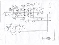
What is in the 'module'? Same as your redrawn schematic of the input stage? But what about T6?my amplifier was based on this plan
Did you use the same early stage power supply rail regulation as the schematics?
🙂
Last edited:
If you talking about BC182B T6 works fine in both cases ...
If you talking about front end supply i use my own.
for main rails i use +/-70-72V trafo 2X50AC
If you talking about front end supply i use my own.
for main rails i use +/-70-72V trafo 2X50AC
Last edited:
Is T6 connected the wrong way around in that? I seem to recall having seen it connected the other way in other schematics.What is in the 'module'? Same as your redrawn schematic of the input stage? But what about T6?
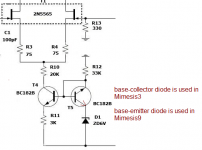
AFAIK the use of uncommon base-collector diode (with emitter tied to base) happened only with Mimesis3. In later models such as the Mimesis9, the common base-emitter diode was used instead.
I simulated both ways in LTSpice to find out if this was accidental or intentional, and I think I found that the uncommon connection (Mimesis original) performs better (very very microscopical tho), may be as a result of different capacitance between b-e and b-c...
But then I didn't like the idea of using noisy 6V zener, so I used different current source (using two-transistor ccs) for the input LTP.
Attachments
AFAIK the use of uncommon base-collector diode (with emitter tied to base) happened only with Mimesis3. In later models such as the Mimesis9, the common base-emitter diode was used instead.
I simulated both ways in LTSpice to find out if this was accidental or intentional, and I think I found that the uncommon connection (Mimesis original) performs better (very very microscopical tho), may be as a result of different capacitance between b-e and b-c...
But then I didn't like the idea of using noisy 6V zener, so I used different current source (using two-transistor ccs) for the input LTP.
Jay , this design is most primitive .
The 2Q (or even a red led) is better (noise vs. PSRR).
I have my design's cascode (symasui) ground referenced off a zener.
It is noisier than a non ground referenced resistive .
Another design uses a LED + a zener , with the led at the cascode bases and
not referenced to ground.
The mirrors higher Z might offset the zener noise ... but this is just a
"quick fix" with many better options. You could get higher CCS Z with
just a resistor ???
The best variant of this input stage is the 3 stage sansui .... with FET's in
the first stage. Vzaichenko uses it in his valve IPS .... I use it in
the Kypton V. Both these beat this design by huge margins.
The distortion (and H2/3/5) is shifted/changed by the LTP Z.
PS- H2/3/5 also changes with amplitude when you tamper with CCS Z.
I wonder why they potted this IPS , to hide it's weaknesses. 😛
Edit - the 20K at the tail shows they were trying to manipulate Z.
OS
What is wrong with the HF? I couldn't stand listening to it.
The sound is stunningly close to this advanced telos 1000 system:
https://www.youtube.com/watch?v=7n7e1u2sVF4&nohtml5=False
Are there any telos 1000 clones out there, by any chance?
Goldmund use darts in their decisions about design options
It was accidental. You see, as shown in the following video:
https://www.youtube.com/watch?v=tjF2O9lbddg&nohtml5=False
Mr Reverchon (the brain behind Goldmund), says that the even had a room with darts to play. They have many targets, each corresponding to a particular options. They throw darts, and if the dart lands on the uncommon option for example, they go with uncommon. If it lands on the common option target, they go with the common. The result is the ultimate sound as shown in the following video:
https://www.youtube.com/watch?v=MPpK-Hj7DPM&nohtml5=False
AFAIK the use of uncommon base-collector diode (with emitter tied to base) happened only with Mimesis3. In later models such as the Mimesis9, the common base-emitter diode was used instead.
I simulated both ways in LTSpice to find out if this was accidental or intentional, and I think I found that the uncommon connection (Mimesis original) performs better (very very microscopical tho), may be as a result of different capacitance between b-e and b-c...
But then I didn't like the idea of using noisy 6V zener, so I used different current source (using two-transistor ccs) for the input LTP.
It was accidental. You see, as shown in the following video:
https://www.youtube.com/watch?v=tjF2O9lbddg&nohtml5=False
Mr Reverchon (the brain behind Goldmund), says that the even had a room with darts to play. They have many targets, each corresponding to a particular options. They throw darts, and if the dart lands on the uncommon option for example, they go with uncommon. If it lands on the common option target, they go with the common. The result is the ultimate sound as shown in the following video:
https://www.youtube.com/watch?v=MPpK-Hj7DPM&nohtml5=False
Jay , this design is most primitive .
Yes. But surprisingly it's the only amp I couldn't "modify"...
hi audio guys ... excuse me guys i want to order the pcb's and build this project but i'm a little scared from that .. i think it's difficult and the thread is huge ... I've build some discrete amps before and some of apex amps but i'm not that experience ...... and I've lost between threads Alex MM at first was building a Single layer version with TO-3 outputs then it became double sided with other package ..... my questions:
* is there specific guide lines i should stick to .. to successfully build this amp?
* is there any mods have done to the final PCB's that Alex mm had post in thread 112 ( i think)
* what should i do after have done soldering to power the amp ( Biasing and dc offsets and so..)
* what about the heating problems that some had faced such that in T7/T8
* one more thing the PART LIST..
thank you and excuse my ignorance
The Telos basically same as Mimesis, except some points:
- LTP Iq is higher, same 4.3mA. The 6V zener of Mimesis instead by LM329 precision low noise 6.9V zener.
- VAS Iq a bit smaller, same 7.8mA for both sides. VAS devices are Zetex transistors, FZT957/FZT857 SOT 223 SMD.
- Individual driver (MJE340/MJE350, but they're KSC2690A/KSA1220A for Telos 5000) for each MOSFET output pair(Exicon ECX10N20/10P20). There are six pairs output per channel.
Based on this info, you can transform Mimesis to Telos.
Walkalone..... i really appreciate your answer ... but i'm realy confused a bout the Mimesis and feel like i'm missing a lot of information so i can't transform it where i've never build it and have this confusion .. if the Schematic and pcb files are available for the Telos then i can study them from the beginning and try to build it...so please if you have them i'd like to give it a try
thanks
thanks
Hallo Vin.
I am not completely in here.
Your Question inspired me to answer.
The Jims Audio store on eBay have had the Telos Boards in his Bare PCB Section
some time back, i have observed.
If you can find the Boards you could also buy LatFet from Profusion in UK and so on.
Cheers Bangla.
I am not completely in here.
Your Question inspired me to answer.
The Jims Audio store on eBay have had the Telos Boards in his Bare PCB Section
some time back, i have observed.
If you can find the Boards you could also buy LatFet from Profusion in UK and so on.
Cheers Bangla.
thanks bangla ... i will consider that but before that i still have the same problem i don't have any construction info directly for the goldmund also some people complained it's fast output stage blown
Vin
Vin
Hi Vin
If you don't trust build a much dissipation F5 amplifier with part Kit from there.
You would not disappointed.
Go to Pass Forum or read the Article about this.
Take also a look how long the thread is- that tells something.
In 100W ultimate Amp thread also happens some movement last time.
Go to inform you can give you some more orientation.
Cheers Bangla.
hi Bangla
thank you any way but . i think i will build the goldmund and take the challenge ... i don't know as much as it's good amp i'm afraid to fail building it ... this thread is all about it but realy i got lost in between lines ... i don't know the test procedure or if there special thing doe to it ... also i don't know has any one build the alex mm single sided pcb at the first of the thread ?
thank you any way but . i think i will build the goldmund and take the challenge ... i don't know as much as it's good amp i'm afraid to fail building it ... this thread is all about it but realy i got lost in between lines ... i don't know the test procedure or if there special thing doe to it ... also i don't know has any one build the alex mm single sided pcb at the first of the thread ?
Hi Vin,
Most of us care about Goldmund maybe are their products price, its very expensive and we think high cost means great sounding too.
Yes, that's not absolute right.
Same as everything of this life, there are no anything perfect.
So, this is DIY forum, let use your knowledge and improves to more perfect.
Trust me, i have few year with clone GM, many guys in my country too.
Hi Walkalone
thnaks for your words walkalone ... i think i got motivated with ur words i feel i wanna try every circuit and pc board i've got .... if i stayed like that i will do ... the problem is me me myself ... my threshold is very low ... as soon as i build the amp and do the test procedure and then it did not work i go very mad and feel like i wanna kill my self
thnaks for your words walkalone ... i think i got motivated with ur words i feel i wanna try every circuit and pc board i've got .... if i stayed like that i will do ... the problem is me me myself ... my threshold is very low ... as soon as i build the amp and do the test procedure and then it did not work i go very mad and feel like i wanna kill my self
- Home
- Amplifiers
- Solid State
- The Very Best Amplifier I Have Ever Heard!!!!