I am eagerly awaiting results. I have been thinking about similar aspects of the design but not combined in the way you have done. Great work!capacitive load on output was tested in post # 30 http://www.diyaudio.com/forums/pass...regation-pass-inspired-ideas.html#post3589317
given the above, i expect that the transformer interwinding capacitances effects (to the extent that they exist) will not be discernible. But we'll verify when we test the sucker.
I will be subjecting the first build to a 'worst-case' PSU with ALL the windings for both channels on one big fat toroid 😀
So no prettied-up results from this one .... honest research is the best kind there is seyz feynman. I'll do my best to present everything i find - warts n all.

I have been running LTSpice simulations of the schematic in post #70 and variations on it, including 1, 2, or 3 FETs per rail. The sims use FQA19N20C for the output MOSFETs, and 2SJ313 for the LTP and current source. In order to compare with other FirstWatt amps, I set the output power supplies to 24V and the (total) bias current to 1.5A.
I have some observations:
I have some observations:
- With the schematic shown in post #70 (LTP degeneration resistors R13, R14, and R20 = 10R, and 2x6800uF caps) the open-loop gain (OLG) is about 750, which is about 2X-3X that of the F5. The caps across the source resistors provide 2.3X increase in open-loop gain above about 200Hz. Thus, without the caps, the OLG is approximately the same as the F5.
- As expected, H2 (2nd harmonic) is non-existent with identical components in the 2 halves of the circuit.
- The OLG can be easily changed by altering the values of R13, R14, and R20. With R13=R14=22R and R20=5000R, the OLG is about 290 with the caps, about the same as R13=R14=R20=10R without the caps.
- H3 is quite low and is largely dependant on the amount of feedback, which is equal to OLG/CLG. Thus, for a fixed CLG, H3 varies with OLG.
thanks lhquam ! Very nice analysis.
Your work shows that we can trade off OLG and degeneration in many combinations. In a 2 stage fast circuit with low fb impedances, the ability to switch between the two become quite flexible.
I do indeed intend to try your suggestions - so far have been a little bit inclined to the caps as I felt they made an audible improvement to dynamics and bass in particular. But on a test bed amp this means little until cased and PSU-ed.
The cool thing is that its easy to try either combination to see what suits 😛 so there will definitely be some more playing about until this is tuned to satisfaction.
Separately, the zero H2 result is what the sims show since they assume perfectly matched fets and passive parts.
As you might have guessed, in practice, there is a fair amount of H2 due to imperfections in matching. IF nulling H2 was an aim - it can be done quite easily by a combination of closer matching and varying the virtual ground resistors to achieve balance. Interestingly, the null seems to remain in place as you vary frequency.
More fun awaits and listening 😀
Your work shows that we can trade off OLG and degeneration in many combinations. In a 2 stage fast circuit with low fb impedances, the ability to switch between the two become quite flexible.
I do indeed intend to try your suggestions - so far have been a little bit inclined to the caps as I felt they made an audible improvement to dynamics and bass in particular. But on a test bed amp this means little until cased and PSU-ed.
The cool thing is that its easy to try either combination to see what suits 😛 so there will definitely be some more playing about until this is tuned to satisfaction.
Separately, the zero H2 result is what the sims show since they assume perfectly matched fets and passive parts.
As you might have guessed, in practice, there is a fair amount of H2 due to imperfections in matching. IF nulling H2 was an aim - it can be done quite easily by a combination of closer matching and varying the virtual ground resistors to achieve balance. Interestingly, the null seems to remain in place as you vary frequency.
More fun awaits
and listening 😀It would mean some rigging, but might i suggest laterals in the outputs? Throw away some gain and get a nice sound in return.
certainly can do - maybe worth to double the drain resistors in the LTP and drop the current thru CCS to suit the lower bias voltage of the lats. so we can keep the input LTP closer to its sweet spot.
or forget all that, just bang in the lats (also reduce current thru CCS) and see what comes out... it will work for sure.....
or forget all that, just bang in the lats (also reduce current thru CCS) and see what comes out... it will work for sure.....
thanks lhquam ! Very nice analysis.
...
I do indeed intend to try your suggestions - so far have been a little bit inclined to the caps as I felt they made an audible improvement to dynamics and bass in particular. But on a test bed amp this means little until cased and PSU-ed.
...
More fun awaits
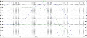
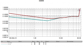
Below 200Hz the caps become less effective. Here is the openloop response for 2 fets per rail, with and without 2x6800uF caps.
Attachments
Heh heh ... looks like a bit of a beast to tame 🙂 - this will be interesting I reckon.
Let me see what sort of fb/caps/no-caps combo I end up with 2 fets & similarly, folks wha are interested can follow along and share their experiences.
Thanks lhquam!
Let me see what sort of fb/caps/no-caps combo I end up with 2 fets & similarly, folks wha are interested can follow along and share their experiences.
Thanks lhquam!
Last edited:
This is also a neat way of illustrating the choices that we, as designers and builders, have.
There is no 'magic' topology or anything in these choices but its nice if the decisions we make are deliberate, informed ones.
The graphs show the effect of more or less feedback. You can see this, for example, by looking at the rolloff point (say -1db roughly vs 1khz) of the bypassed vs unbypassed cases above.
The unbypassed case has lower gain but also you get a higher rolloff point. This sort of tradeoff looks familiar. So we realise that what we are seeing is no coincidence - it achieves this higher bandwidth through the action of localised feedback provided by degeneration.
Ultimately, the total amount of 'raw' gain you get is set by the devices, operating points and topology. Then you have to decide how much of this gain you will give up through local feedback (via degeneration) vs how much through loop feedback.
With complex topologies, stability issues often make the answer pre-ordained.
With a simple topology, we have some freedom to decide. Pretty cool to have some choices, I think.
Last edited:
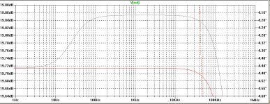
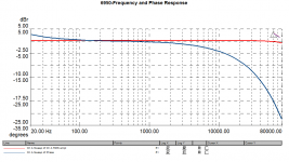
Here is the closed-loop response, with and without the caps. (R13=R14=12R, R20=500R). As you can see, the shape the curve with caps resembles to corresponding open-loop curve, but there is only a 0.14dB difference from the the curve without the caps.
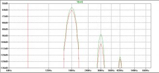
Also shown is the harmonic distortion spectrum at 60Hz (middle) and 1kHz (right), 10 watts into 8 ohms, without (green) and with (red) caps. In the 60Hz spectrum, the caps decrease H3 by about 3dB and H5 by about 12dB. In the 1kHz spectrum, the caps decrease H2 by about 2dB and H3 by about 1dB.
I am a little surprised by the H2/H2 decrease with the caps at 60Hz where I would expect the caps to have less impact than at 1kHz.
Attachments
Hi lhquam - I'm not too sure re the relative results 1k vs 60hz.
But as a matter of interest,
the measured FFTs at 10w into 8 ohms show H3, H5 etc all 20db lower than the ones you posted above. Usually real world results are worse than sim not better. Maybe the reasons are due to different op devices in my design vs the sim above Or maybe due also to other changes in the sim - not too sure.
I have H2, H4 also (which the sim does not show) but we already discussed the reason earlier why this is the case.
cheers!
We are probably comparing the circuits with significantly different parameters. For instance my total bias current is 1.5A, and voltages are 24V. Let me know the parameter values in your build, including which FETs, bias currents, and voltages were used.Hi lhquam - I'm not too sure re the relative results 1k vs 60hz.
But as a matter of interest,
the measured FFTs at 10w into 8 ohms show H3, H5 etc all 20db lower than the ones you posted above. Usually real world results are worse than sim not better. Maybe the reasons are due to different op devices in my design vs the sim above Or maybe due also to other changes in the sim - not too sure.
I have H2, H4 also (which the sim does not show) but we already discussed the reason earlier why this is the case.
cheers!
 .
. Hi lhquam - I'm not too sure re the relative results 1k vs 60hz.
But as a matter of interest,
the measured FFTs at 10w into 8 ohms show H3, H5 etc all 20db lower than the ones you posted above. Usually real world results are worse than sim not better. Maybe the reasons are due to different op devices in my design vs the sim above Or maybe due also to other changes in the sim - not too sure.
I have H2, H4 also (which the sim does not show) but we already discussed the reason earlier why this is the case.
cheers!
It just occurred to me that I did not show H1 in those plots. H1 was at +19.2dB in each case, which is consistent with your results.
Now its time to prepare the home for the new amplifier.
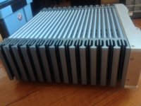
Here are some pictures .....
I promise she doesn't suspect a thing 🤐
What make amp is that? Beautiful !!
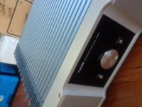
I love the heatsinks, even if there are the wrong color!
Rush
I bought her about 3 years ago when i first moved to Hong Kong. I bought them blind (ie un-auditioned) - reviews I saw were pretty good, and specs were :
FREQUENCY RESPONSE: 10Hz – 100Khz (+0, -3db)
TOTAL HARMONIC DISTORTION: <0.04%
S/N RATIO: >95db (A WEIGHTED)
POWER OUTPUT: 100W x 2 (8 Ohms)
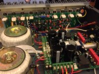
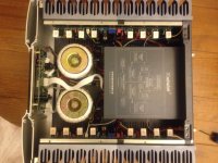
Plus looking at the insides, it looked like quite a sophisticated piece of work. Class A, cfa type topology (claimed) and generally pushed all the buttons. Big heatsinks to boot. The cost (then) at $500 bucks was just too good a deal to pass up.
The listening experience was a little less than successful however.
After a few days of excited messing about, I just found myself disinterested in listening much. The details seemed all there but imaging was flat and one-dimensional. Some reviewers spoke of the smoothness - and I couldn't disagree but then again there may be too much of a good thing. I felt that the dynamics were pancaked and i had to keep turning it up to get things bopping along. When turned down to civilised listening volumes you got a feeling that transients were being truncated somehow so it was like the pizzazz without the zazz.😀
i cracked it out recently, listened again and found that it certainly didn't improve just ageing in the dark....
FREQUENCY RESPONSE: 10Hz – 100Khz (+0, -3db)
TOTAL HARMONIC DISTORTION: <0.04%
S/N RATIO: >95db (A WEIGHTED)
POWER OUTPUT: 100W x 2 (8 Ohms)
Plus looking at the insides, it looked like quite a sophisticated piece of work. Class A, cfa type topology (claimed) and generally pushed all the buttons. Big heatsinks to boot. The cost (then) at $500 bucks was just too good a deal to pass up.
The listening experience was a little less than successful however.
After a few days of excited messing about, I just found myself disinterested in listening much. The details seemed all there but imaging was flat and one-dimensional. Some reviewers spoke of the smoothness - and I couldn't disagree but then again there may be too much of a good thing. I felt that the dynamics were pancaked and i had to keep turning it up to get things bopping along. When turned down to civilised listening volumes you got a feeling that transients were being truncated somehow so it was like the pizzazz without the zazz.😀
i cracked it out recently, listened again and found that it certainly didn't improve just ageing in the dark....
rush yeah the color certainly err a touch feminine maybe ?
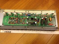
But i have lots of respect for folks who do this for a living and put food on the table with their efforts. So no sniping from the aisles here. As you can see engineering and value is just unbelievable.
Even ignoring all the preamp and selector bits (servo controlled volume pot on a $500 amp - really ??) and casing - this is a really fancy dual differential design by the ooks of it. Each channel has like 20 small signal transistors, one audio grade opamp (socketed to facilitate tweaking), 6 to-220 drivers/vbe stage etc, and 8 output devices ! Phew .....
I wanted the case so too bad all this is going into magic "it-will-come-in-handy-someday" box - I say magic because nothing ever comes out again!
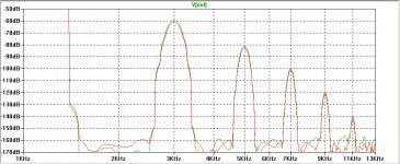
Before gutting the innards though, I also made some measurements with the Prism system. The results were a bit surprising tbh... or maybe not.
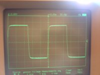
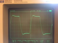
The one I have doesn't get anywhere close to the rated 100W. 10k square waves into 8R load and then with a 3uf cap also shown. Looks a bit odd given teh bandwidth.
I assume that the specs claimed are honest, so that must mean that i have a duff unit.
I guess every manufacturer has a few dud ones - if i had known enough to complain 3 years ago i may have had a better outcome.
Anyway no sense crying - maybe with some new bits she might do better......😱
But i have lots of respect for folks who do this for a living and put food on the table with their efforts. So no sniping from the aisles here. As you can see engineering and value is just unbelievable.
Even ignoring all the preamp and selector bits (servo controlled volume pot on a $500 amp - really ??) and casing - this is a really fancy dual differential design by the ooks of it. Each channel has like 20 small signal transistors, one audio grade opamp (socketed to facilitate tweaking), 6 to-220 drivers/vbe stage etc, and 8 output devices ! Phew .....
I wanted the case so too bad all this is going into magic "it-will-come-in-handy-someday" box - I say magic because nothing ever comes out again!
Before gutting the innards though, I also made some measurements with the Prism system. The results were a bit surprising tbh... or maybe not.
The one I have doesn't get anywhere close to the rated 100W. 10k square waves into 8R load and then with a 3uf cap also shown. Looks a bit odd given teh bandwidth.
I assume that the specs claimed are honest, so that must mean that i have a duff unit.
I guess every manufacturer has a few dud ones - if i had known enough to complain 3 years ago i may have had a better outcome.
Anyway no sense crying - maybe with some new bits she might do better......😱
Attachments
Last edited:
- Status
- Not open for further replies.
- Home
- Amplifiers
- Pass Labs
- The Valorous Amp - A modest aggregation of pass inspired ideas