The Valorous Amp - A modest circlotronic aggregation of pass inspired ideas
EDIT>>
Latest schematic is here:
http://www.diyaudio.com/forums/pass...gation-pass-inspired-ideas-2.html#post3594179
Hullo,
Here is the little result from a *LOT* of work these last 6 mths. Most of my time was spent finding out how NOT to make a hi-end amplifier with few parts that works well.. Until now 🙂
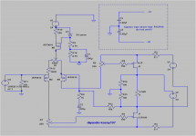
This is a simple circlotron with ideas culled from some of the excellent work by the august authors in this forum (with some small contributions from myself.) You can see shades of Rotharcher's AFC, NP's Aleph input diff stage & F6 thots plus some ideas for the CCS from Horowitz & Hill too for good measure.
As you can see, I am making no claims for originality 😀
One of the nice things (to me)of this cct is that it takes unbalanced inputs directly & the output offset is well behaved. There is also very good symmetry if that keeps things on balance for you lols ...
The circuit works well and you can use hitachi laterals as well if you prefer instead of the semisouths. Jfet inputs will be played with another time as I'm quite happy with it as is.
The bias set and diff pots allow you to set up bias and harmonics to your liking. [edit- not quite true with this schematic - see post #9] I chose not to set the bias by varying R10 as the open loop distortion of the LTP ip stage is quite sensitive to the voltage across R6 and R7.
BTW., if you don't bypass the power rails, the amp will oscillate. For sure. I mean it will - really. Anyway....
V1 and V2 are the beefy rails. For V3 you can use pretty much anything as the current drawn is minimal.
Gain is double that implied by a cursory look at the FB resistors as the FB network sees only half the output amplitude.
Any questions/brickbats pls fire away! I'll be travelling soon so bear with me for any short delays in responding.
ps. the schematic is not simmable directly as I am quite unskilled at LT spice so don't know how to insert pots properly so these were hard-drawn 😱
EDIT>>
Latest schematic is here:
http://www.diyaudio.com/forums/pass...gation-pass-inspired-ideas-2.html#post3594179
Hullo,
Here is the little result from a *LOT* of work these last 6 mths. Most of my time was spent finding out how NOT to make a hi-end amplifier with few parts that works well.. Until now 🙂
This is a simple circlotron with ideas culled from some of the excellent work by the august authors in this forum (with some small contributions from myself.) You can see shades of Rotharcher's AFC, NP's Aleph input diff stage & F6 thots plus some ideas for the CCS from Horowitz & Hill too for good measure.
As you can see, I am making no claims for originality 😀
One of the nice things (to me)of this cct is that it takes unbalanced inputs directly & the output offset is well behaved. There is also very good symmetry if that keeps things on balance for you lols ...
The circuit works well and you can use hitachi laterals as well if you prefer instead of the semisouths. Jfet inputs will be played with another time as I'm quite happy with it as is.
The bias set and diff pots allow you to set up bias and harmonics to your liking. [edit- not quite true with this schematic - see post #9] I chose not to set the bias by varying R10 as the open loop distortion of the LTP ip stage is quite sensitive to the voltage across R6 and R7.
BTW., if you don't bypass the power rails, the amp will oscillate. For sure. I mean it will - really. Anyway....
V1 and V2 are the beefy rails. For V3 you can use pretty much anything as the current drawn is minimal.
Gain is double that implied by a cursory look at the FB resistors as the FB network sees only half the output amplitude.
Any questions/brickbats pls fire away! I'll be travelling soon so bear with me for any short delays in responding.
ps. the schematic is not simmable directly as I am quite unskilled at LT spice so don't know how to insert pots properly so these were hard-drawn 😱
Attachments
Last edited:
Have you tried compensating the diff pair vs. the output for that osc problem? Or bigger gate stoppers or miller at the output?
You have no temp comp? Is it that the R100 and your input pair do well enough without any?
Alas it is not a follower? I have Circlotrons in my head as followers? I personally think we should dream up another name...
You have no temp comp? Is it that the R100 and your input pair do well enough without any?
Alas it is not a follower? I have Circlotrons in my head as followers? I personally think we should dream up another name...
Have you tried compensating the diff pair vs. the output for that osc problem? Or bigger gate stoppers or miller at the output?
You have no temp comp? Is it that the R100 and your input pair do well enough without any?
Alas it is not a follower? I have Circlotrons in my head as followers? I personally think we should dream up another name...
I did not end up with any compensation caps since the source of the oscillation seemed to be poorly bypassed power rails. I added some caps as shown in the little box in the schematic and then all was well. I used 0.47uf caps as that was what I had in my box. Fingers crossed 🙂 There's not much OLG hence fb is quite low so there's a decent chance we can do without 'em.
And you're right - it's not a follower - there are a few examples of circlotron output stages like this - eg the excellent circlotron by Mike Rothacher which is on the passdiy website - recommended reading! The simplest follower type circlotron using enhancement Fets is probably the one on audiodesignguide.com but that approach leaves us with the voltage gain stage to deal with (well, we can always use tubes as he has)
As regards temperature compensation - I did use the R100s for the outputs and suggested the hitachi laterals (2sk1058) as an alternative. The F6 thread has some very good discussion of this point and these are equally applicable here.
Turns out that its not that easy after all to play with the harmonics balance and nulling in my design - the F6 really rules here 🙂 I think the only way to do it properly is to have separate biasing and capacitor coupled ac drive - maybe I will add that to a to-do enhancement list after i get the basic design properly nailed down.
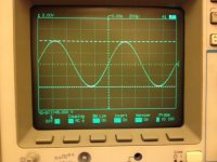
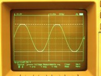
For now, things are progressing well. Sine attached and picture of the amp clipping at 47V attached as well. Can't see any signs of sticking or wobbelies during clipping so this should sound quite clean on transients.
At this point the circuit is exactly per the schematic. The pot on the diff pair source was left at very close to center and later when I get matched fets for the input I will ditch the pot altogether.
One thing I notice is that HF response is *NOT* great - its down 1.4db at 20khz. I know that would not be audible but still its annoying so I'll try to spend some time figuring out why. I think it could be down to either the input capacitance of the LTP mosfets and/or the bypass caps. These caps see audio signals so that may certainly be a factor but if I get rid of them the amp has a tendency to oscillate. Am trying smaller values & also different locations (ala FLG's suggestions) to see if I can do better - any ideas here would be welcome! Very large gate stoppers would prob work but the performance expense would be be considerable imo.
[unproven speculation alert] I think that circs have more tendency towards this as a spike in one half induces an opposite going spike in the other. With complementary op stage - this snuffs out the oscillation as both halves need to see the same phase drive to amplify. With circs, the opposite phase spikes get amplified and then that sets things off. Thats my theory anyway! So if that is true, then some sort of bypassing will be essential - the trick is finding out the most optimal way to do it...
Attachments
Some gate stoppers on the input MOSFETs? 200ohm maybe? Bypass your R12 with a tiny cap? 10p maybe? 😀
The Power Supply could also be causing issues. I beleive N.P. said the F5 was not tolorent of caps right on the output transistors. It caused osc.
The Power Supply could also be causing issues. I beleive N.P. said the F5 was not tolorent of caps right on the output transistors. It caused osc.
Last edited:
Just a small update on things. Thanks to the suggestions on-list and off-list, I've removed C1, C3 and C4. Yes, the dreaded 'bypass' caps are gone (well for the moment).
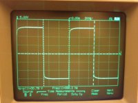
The input fet (M4) has had a 1k resistor added in line with the gate, and I've increased the gate stoppers for the Jfets to 470R for now. I kept the -ve rails as far away from the outputs as I could and the amp is now very stable. Square wave testing is also clean with the larger stoppers. HF performance is not yet optimal (you can see some small rolloff on the leading edges).
Overall I'm pretty amazed how well such a simple circuit does - with the basic config proven, I'll go ahead and do a PCB for further work to take place... if anyone with PCB experience wants to take a stab that would be most welcome else its a transparency sheet, layout tape and marker pens for me (dates me a bit i know!)....
ok time for a small update and a question. I have pretty much finished with this configuration and now have moved to using two feedback networks instead of one - this was important as it gave the opportunity to reduce/eliminate the large 100R resistor from the source of the LTP. Otherwise you end up locked into having to use the same values in the virtual earth network and the source resistors. You can see the dilemma...
Anyway, with balanced fb loops we get rid of this interdependency (and create a few more but manageable ones) and I am now pretty happy with the outcome.
One of the things I am trying now is to find current production fets for the input LTP so that anyone trying to make this doesnt have to deal with unobtainable parts.
I have tried SJ74s, SJ313s and they both work well (the latter is pretty excellent imo) but are nla. I've tried most of the usual IRF 96xx IRF, 95xx suspects but they didnt do so well. IRF9Z24 worked well. Small devices tend not to have much Gm so that is why I am looking at To-220 types generally.
BJts I have tried here didn't work so well for me - measured distortion was great, sounded a bit leaden in my setup and other issues due to base current that I'm not eager to deal with.
Basically I need a current p channel fet with highish Gm > 0.5S or higher at low currents (3-10ma) with low/flat capacitance - impossible ask ? Anyone any ideas ?
Sic Fets
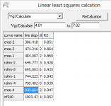
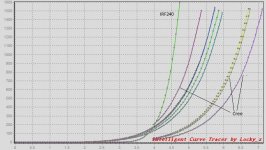
I was playing around with some different input/output fet combos and will post results later when properly digested. Some of the outputs that i tried were the new (and expensive) Sics from Cree and Rohm. I measured them on a curve tracer and also put a trace of our workhorse IRF240 for comparisons.
I bought 4 of each - unsorted other than being in the same order. So the general observation based on a very limited sample size is that the Crees have very low transconductance and relatively widely dispersed Vgs and Gm. The exact device was CMF10120.
The Rohms were SCT2080KE and measured quite ok IMO. Dispersion was fairly good and the reason you see only three traces is that there was a pair that measured almost identically. Gm was a bit better than the crees but still nothing compared to the 240s.
These sorts of comparisons are not the whole enchilada of course but I will be measuring these in-situ in the amp and we can compare the results in a working amp and see how they get on.
Graphs attached - first is the Gm and second are the traces. You will notice the 'outlier' cree as the second trace from the left. The umarked ones are the SCTs.
Attachments
Start of mini-article - clever chappies pls skip
Ok so I've been meaning to write up the notes I had compiled on this, so before pressing on with the latest practical results and things, lets take a look at some of the building blocks that I used for this amp.
We'll start with the circlotron output stage first and then work backwards to the input stage. Almost all of the circ material is covered well in at least two other places so I am only going to provide a potted version so that the final circuit is easier to follow. The two places ? M. Rotarchers article and the really excellent Tubecad website.
So what is this type of stage and why do we want it ? The attraction is that it uses identical polarity parts for push-pull action that is required for us to swing electricity through the loudspeaker load.
Why the interest in identical polarity parts ? Well, what would be perfect would be output devices which amplify AC signals identically but differ only in their polarity. Unfortunately these things don't quite exist at this time so why not just use the same devices 😀
There are only very few ways of getting these like-polarity devices in push-pull to also deliver voltage gain. The really excellent F6 shows one approach and the circlotron is another. The transformer coupled output stages similar to those used for tubes would be a third. I am saving that for my next amp 😉
This attached schematic shows what the basic output stage looks like.
[Next post:- how it works]
Attachments
Last edited:
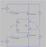
Let's start with the bottom fet. The first part of the sinewave we can see in Input-2 is going LOWER in amplitude and as a result, the Vgs of the bottom fet starts to drop. This makes it conducts less. As a consequence, the voltage at L2 moves further away from the negative rail of V2 and now becomes more POSITIVE with respect to the arbitary ('virtual') ground we created at the junction of R2 and R3.
At the same time, at the top fet, the inverted signal is going HIGHER in amplitude (turn the monitor upside down if you dont believe me) so the Vgs of the top fet starts to rise. This makes the top fet conducts more, dragging L1 closer to the negative rail of V1 - causing L1 to go more NEGATIVE wrt ground. So we have L2 going more +ve at the same time that L1 is going more -ve and current starts to flow through the load ! There we have it: a pertubation at the input causes a bigger one at the output.
How much bigger ? By two times the transconductance of the fet multiplied by the resistance of the load. So if we used a Fet with a Gm of 2 siemens and an 8 ohm load, we would get a stage gain of 32x.
In many ways you can think of this as being two single-ended amplifiers sitting one on top of the other. See the zen ones - they work the same way - we have just rearranged the voltage rails and as a consequence, gotten rid of the current sources.
Like in the zen articles also, we now have to find a way to drive these big beastly fets and set up the bias voltages we want at the same time. M Rotarchers Amazing Fet Circlotron shows us one very cool way of doing this - we will try another.
Oh, we also need to figure how to do the phase splitting so that we can use our lovely phono-stage too in addition to balanced inputs.
[Next post;- the genesis of the input stage]
Last edited:
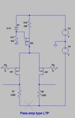
Input input
In thinking about an option for driving the fets, it seemed reasonable to try and adapt something that already worked well. So I turned to the Long Tailed Pair design used by NP for many many of his successful amps in the 90s and noughties.
He tasked it to drive OP stage FETs directly so that was a good start - but the problem was obvious - i needed to 'split' the negative rails since the source references of the op stage were not conjoined as it is for his designs.
At that point I was not yet spice conversant and so many failed experiments ensued....
Some dead-ends [and dead fets] later, I wondered if it would work if i just cut along X (heh) and added another voltage source😕
[edit: see figure 15 and text in NP's DIY Opamp article http://www.firstwatt.com/pdf/art_diy_opamp.pdf to understand the constant current source bits M5, R17, 18 and D1]
Attachments
Last edited:
- Status
- Not open for further replies.
- Home
- Amplifiers
- Pass Labs
- The Valorous Amp - A modest aggregation of pass inspired ideas