Let’s plug in a few guesstimated values and see what we get:
Let’s assume:
Power Dissipated = 80 W
Ambient Temp = 25 C
Theta(Heatsink-To-Air) = .3
Theta(Bracket-To-Heatsink) = .1
Theta(Case-To-Bracket) = .3 (Kapton & Grease)
Theta(Junction-To-Case) = .7 (Guess For Super TO-3)
That would give us a chip temp of:
TA+PD*(THA+TBH+TCB+TJC)
=25+80*(.3+.1+.3+.7)
=25+80*(1.4)
=137 C
And you can guestimate the temperature of everything else from there:
Heatsink will be (roughly) at 49C, Bracket will be at 57C, and case will be at 81C
See where you're off and you know where to start improving. 🙂
Heatsink will be (roughly) at 49C, Bracket will be at 57C, and case will be at 81C
See where you're off and you know where to start improving. 🙂
I have no any temp meter so I do not know exact the degree🙁
Thank Mike for good formula about the temp😉
Thank Mike for good formula about the temp😉
It's normal for the case of the transistor to feel much hotter than the heatsink, one will be touchable, the other will not. It's possible your thermal interfaces are fine, but you can't know for sure until you measure. The temperature probes that come with inexpensive DMM's would be adequate, maybe even a cooking thermometer if you have one of those around. Have fun 🙂
I finished two mono block, have some test with ATC SCM50 loudspeaker and compare with Ironamp + Sony VFET P2. I will show the temp measure and review the sound later...😛

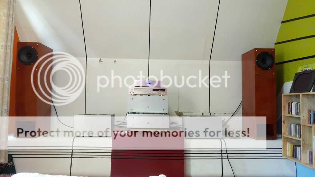


Here your diffusor🙄

Wow! Gorgeous!
More pics, and I love that diffusor. 🙂


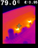
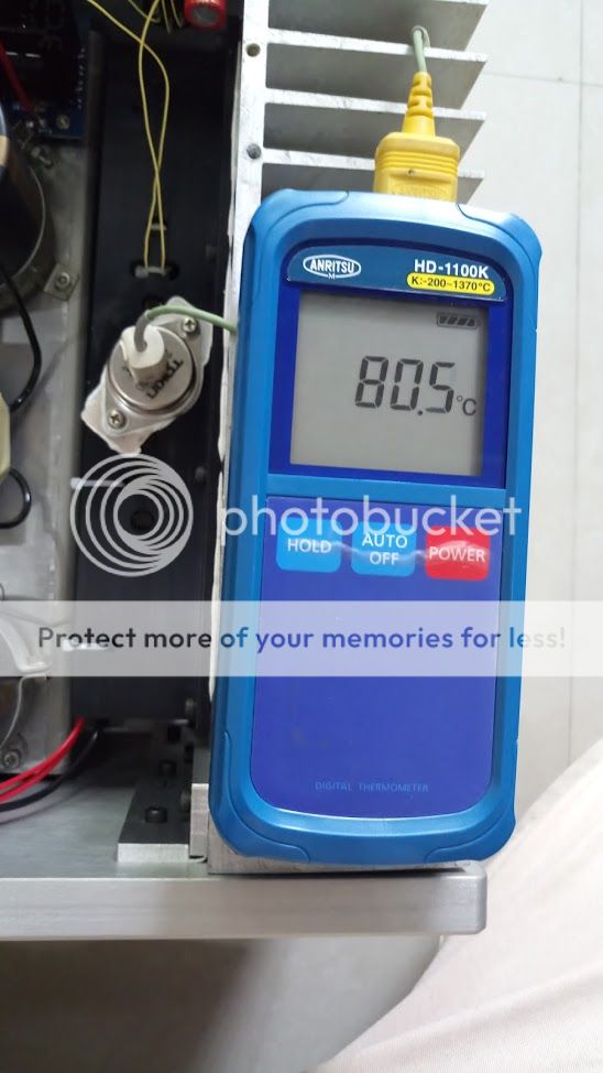
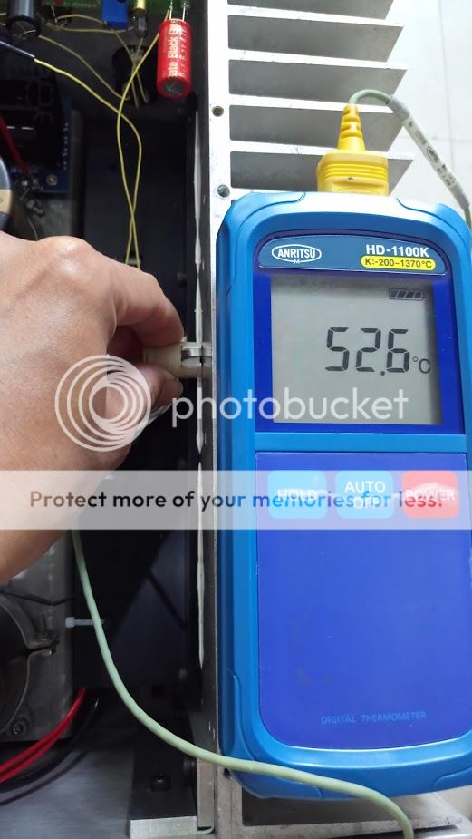
Some images: on the VFET, on the T bracket close to VFET and on the heatsink close to T bracket (at 1.5A bias)
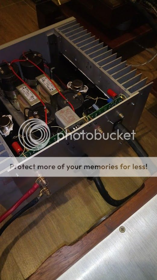
I combined two mica of TO-247 size for insulator. Unfortunately, the new material insulator from Panasonic (graphite) is so thin (the thickness is 0.5mm = 0.01mm graphite + 0.506mm adhesive) => easy to short circuit and thermal conductivity is hard to transfer through thick adhesive layer. I bought a new graphite (0.1mm) without adhesive and test later.
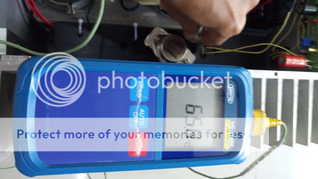
I combined two mica of TO-247 size for insulator. Unfortunately, the new material insulator from Panasonic (graphite) is so thin (the thickness is 0.5mm = 0.01mm graphite + 0.506mm adhesive) => easy to short circuit and thermal conductivity is hard to transfer through thick adhesive layer. I bought a new graphite (0.1mm) without adhesive and test later.


I have a plan to build a new mono block VFETRON 75 for my friend with lower power supply and higher current bias (2.5A to 3A) for easy to drive ATC loudspeakers.
@Mike: you was right, the temp on VFET never the same the temp on heatsink😛
@Mike: you was right, the temp on VFET never the same the temp on heatsink😛
Hello Nagini
Well done 🙂
How much is temperature difference mica or graphite compare with grey silicon rubber pads ?
Greetings
Well done 🙂
How much is temperature difference mica or graphite compare with grey silicon rubber pads ?
Greetings
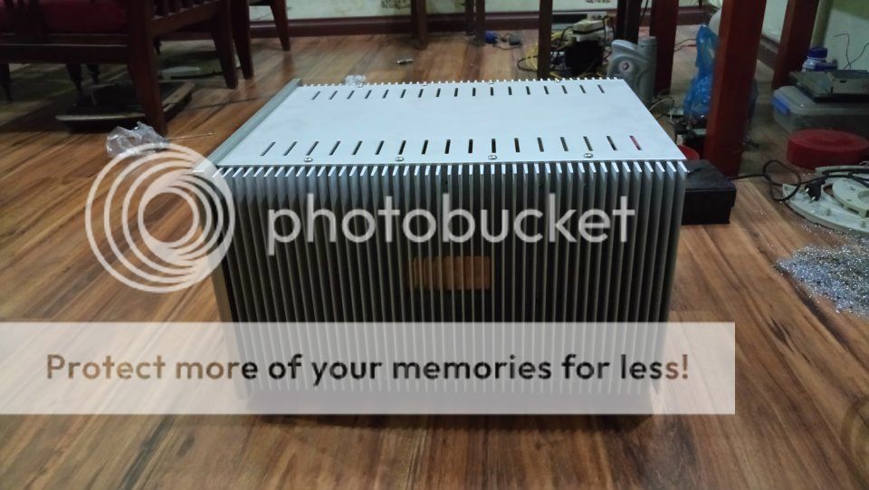
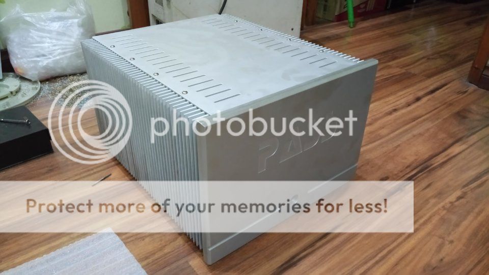
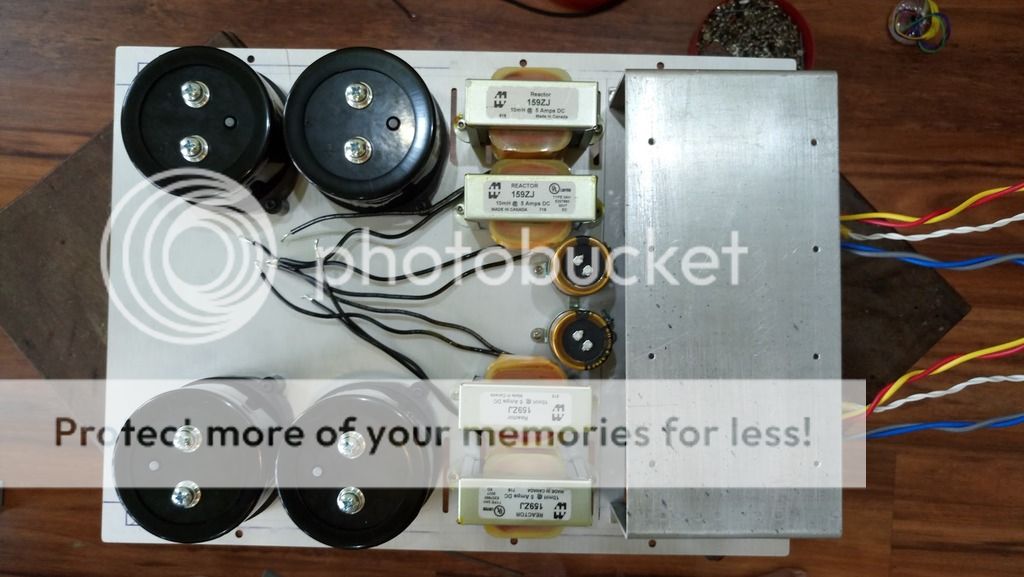
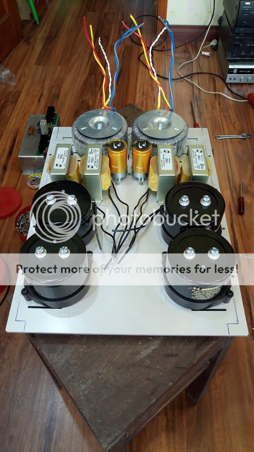
As I said, I'm trying to build a second VFETRON 75 with higher bias and better parts. Now, the first mono block is going to finish as below, hope all of you love to see it. I will update more later
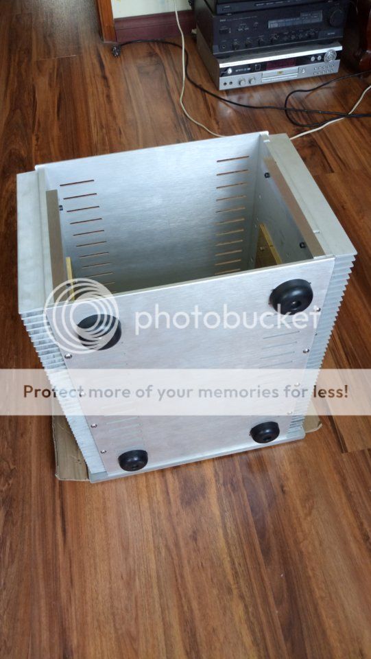
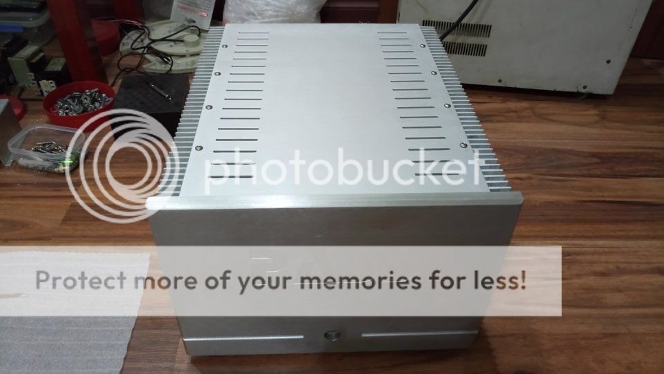
Very nice Nagini, love the enclosure. How did you produce your frontpanel? Is it two 10mm plates on each other?
I build this amp for my friend. I told him this amp from Mike and I want to mark VFETRON on the front panel but my friend is a fan of Nelson, so I used the STOP font for that😉Very nice Nagini, love the enclosure. How did you produce your frontpanel? Is it two 10mm plates on each other?
The front panel is a copy of Pass XS series and it's 15mm thick.
- Home
- Amplifiers
- Pass Labs
- The V-Fetron Comes To Life