I just wanted to give everyone an update as to where things are with v1.2 of the board.
This board accepts multiple models of low voltage regulators, of these models there are two base variants. MIC29XX2 models where pin 1 is a simple enable pin, and MIC29XX3 models where pin 1 is an error flag used to sense error conditions on the output. We've been tweaking the schematic and board to incorporate usage of the error flag while maintaining functionality of the MIC29XX2 models. Selection of models will be controlled by a few different jumpers.
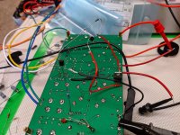
In the image below is some testing where I've hacked some transistors in as a high side switch after the 7805 regulator for the high voltage delay circuit. When using an MIC29XX3 model, if the MIC enters an error condition (we have been testing by overcurrenting the chip), the red LED will turn on, and cut 5V output to the high voltage delay circuit, which will turn off high voltage output. Only a few inexpensive components to add extra protection is worth it in my mind.
This board accepts multiple models of low voltage regulators, of these models there are two base variants. MIC29XX2 models where pin 1 is a simple enable pin, and MIC29XX3 models where pin 1 is an error flag used to sense error conditions on the output. We've been tweaking the schematic and board to incorporate usage of the error flag while maintaining functionality of the MIC29XX2 models. Selection of models will be controlled by a few different jumpers.
In the image below is some testing where I've hacked some transistors in as a high side switch after the 7805 regulator for the high voltage delay circuit. When using an MIC29XX3 model, if the MIC enters an error condition (we have been testing by overcurrenting the chip), the red LED will turn on, and cut 5V output to the high voltage delay circuit, which will turn off high voltage output. Only a few inexpensive components to add extra protection is worth it in my mind.
Attachments
Gents - awesome work on this! Thanks for all the time and effort you put in. Is this now at a stage where we can order boards to build? Or still some more beta testing needed? I'm also happy to help with that.
Thanks psmith001, I am hoping to have a finalized board ready in the next day or two. Right now I am working on cleaning up the layout a little bit to see if I can get the board a bit more compact, then I'll revisit the BOM to make sure it's 100% accurate, then I'll be able to share gerbers with everyone.
The extra protection when using an MIC29XX3 model regulator mentioned in post #81 did not have consistent behavior, and the only way we could figure incorporating it would be to have it's own dedicated power supply, and given the scope of the project that seems a bit much, so we've canned that extra protection and reverted back to the original idea of just a jumper to select which model low voltage regulator.
The extra protection when using an MIC29XX3 model regulator mentioned in post #81 did not have consistent behavior, and the only way we could figure incorporating it would be to have it's own dedicated power supply, and given the scope of the project that seems a bit much, so we've canned that extra protection and reverted back to the original idea of just a jumper to select which model low voltage regulator.

I've just updated the main post with the finalized v1.2 based on the LM317 regulators, the BOM, and gerbers with and without via's have been attached.
I'll get to work on the LR8N-3G based model in a few days, no ETA at this point as to how long it will take to get that variant going.
I'll get to work on the LR8N-3G based model in a few days, no ETA at this point as to how long it will take to get that variant going.
Yes BH has done a good job on this board - $10.90 USD for 5 off at JLCPCB plus freight, same price for vias or no vias.
Great job BH and Gary.  This type of board is much needed. That you have placed it in the public domain is doubly great!
Did you test the board posted in the first post?
This type of board is much needed. That you have placed it in the public domain is doubly great!Did you test the board posted in the first post?
Can a HV supply be used without relays, by jumping with wire points RL1 + RL2 on HV B+ side ?
I think that would work just fine.
If you don't want the HV delay, then you do not need to load any of the components in the HV relay delay circuitry in the bottom third of the schematic, saving some money. As you mention link the contacts on the relay with a jumper.
BH, has built and tested the rev 1 board, the rev 2 board is the same but slightly smaller - BH can add more here., with any specific details.
BH, has built and tested the rev 1 board, the rev 2 board is the same but slightly smaller - BH can add more here., with any specific details.
Last edited:
Thank you for this wonderful job! I am new here and have some questions that might be obvious for most user here but not for me. What would be the maximum output voltage from transformer I can use with this PSU? If I use transformer with a 100 V output then what would be the max voltage I get out from this PSU? 🤔
The highest voltage transformer you could get away with would be about 280V which would get you close to the max 400V. With a 100V transformer, depending on your current draw, R13 filter resistor value, you'd probably cap out around ~130V max output. You could adjust the filter resistor size to fine tune this a little.
This looks like a great board! Great job!
Are the low voltage heater/filament outputs isolated from each other? For example, necessary if using DHT’s.
Are the low voltage heater/filament outputs isolated from each other? For example, necessary if using DHT’s.
Does anybody know what is the PSRR for the high voltage output and for the low output?
Output noise voltage? Any other feedback who have used it?
Output noise voltage? Any other feedback who have used it?
I don't sorry, I believe gary s is running a few of them, and has spoken highly. I had to back burner several projects due to winter and needing to get other stuff within my household under control.
I do intend when I get time to measure that stuff, if anyone can point me towards a guide in doing so that would be grand.
I do intend when I get time to measure that stuff, if anyone can point me towards a guide in doing so that would be grand.
Last edited:
- Home
- Amplifiers
- Power Supplies
- The Ultimate Tube Preamp Power Supply