The LM723 has been around for a long time and is a fine regulator, some people might balk at the price of the metal can version though. A quick look around at the usual suppliers only shows the metal can version in stock at up to $20.00 each with none showing the plastic DIP packages available.
The LM723 has been around for a long time and is a fine regulator, some people might balk at the price of the metal can version though. A quick look around at the usual suppliers only shows the metal can version in stock at up to $20.00 each with none showing the plastic DIP packages available.
We might be in luck. I took a look through the datasheet at the different packages available for the UA723 which as far as I can tell is the same as the LM723.
https://www.mouser.com/ProductDetail/Texas-Instruments/UA723CN?qs=dQtLEVC3WobAwR7%2B9iQPkw==
https://www.mouser.com/ProductDetail/Texas-Instruments/UA723CNE4?qs=0O/ZFlpUpJVqU29MbGgyaA==
Quite cheap and seems to be readily in stock!
Frequency Comp cap may need to be a little larger, depending on final output voltage, I havent fully tested this design
a small amount of feedback may be nessessary from the unregulated side to the grid of V1.2, a simple resistor between 4.5M and 10M, this will keep the drive to the pass tube stable.
This setup will allow for a lower output impedance driving the pass tube with a cathode follower.

The floating design found in the TI datasheet works quite well, I would add a Zener Follower to the Vcc, this should improve the PSRR considerably!That is a neat circuit, something to keep in mind for the future for sure. For now I'd like to stick with the idea of a floating 723 since it's low noise is so attractive. Hopefully component footprint can be kept similar to an LM317 maida circuit.
Hi, kicking in an open door. It is possible to use the TLC556 and reduce size of the board and still have the flashing LED.We aren't going with any programmable chips at this point, right now looking at a variation of Pete Millett's muting delay circuit. eg: a 555 timer to control a 250v relay with the contacts in series like Rod Elliott's circuit shows. I've drawn up Rod's but since it uses a 16dip CMOS timer, I feel it will have a larger footprint, and I think I can have a smaller footprint with a riff off Pete's circuit. Essentially the top half of the attached circuit as I don't think we need the footprint of the LED portion unless other people want me to include that. Where I am unsure is, can I tap off the rectified filament DC current that has ground elevated to 1/4 B+ voltage, and run the high voltage delay circuit with an elevated ground? That would save on components in the circuit.
View attachment 1082403
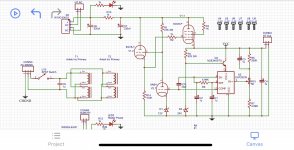
I wanted to get a quick update for everyone, been hard at work on this, but like all things DIY it's going a bit slower than I anticipated. So as not to clutter up this thread with me learning, a kind user has been helping me outside of this thread and here's the current schematic with a v1.1 update as far as changes and what's next.
** v1.1 Update **
** Working On **

** v1.1 Update **
- Custom footprints for all high voltage resistors
- Supports Yaego FMP 3W and Vishay PR03 3W
- FMP preferred due to slightly temperature coeffecient
- Dual pin pitch electrolytic capacitor footprints to allow as wide a variety of choices as possible
- 5.08mm pin pitch terminal blocks for all inputs / outputs
- Loop breaker revamped
- Removed original schematic components
- Replaced with a CL-60 NTC Thermistor and parallel 0.022uF 300+ VAC Y2
- Filament regulator circuit refined
- Supports two variants of MIC29xxxWT, selectable via J6, 1-2 for MIC29X02WT, 2-3 for MIC29X03WT
- MIC29X02WT
- MIC29X03WT
- Choose based on current needs and part availability
- Models ending in 2 have an enable flag for pin 1
- Models ending in 3 have an error flag for pin 1
- I think per the datasheet this would light up an LED D12 if an error is flagged
- https://www.mouser.com/datasheet/2/...75x_High_Current_Low_Dropout_Regu-1889172.pdf
- sections 4.5 and 4.6
- I'm hoping someone can confirm
- https://www.mouser.com/datasheet/2/...75x_High_Current_Low_Dropout_Regu-1889172.pdf
- Trim potentiometer terminated to ground
- Allows for range of 1.24VDC to 13.64VDC
- Jumper J4 voltage doubler, 1-2 for double, 2-3 for normal
- Filament ground elevated to 1/4 B+ voltage
- Supports two variants of MIC29xxxWT, selectable via J6, 1-2 for MIC29X02WT, 2-3 for MIC29X03WT
- Changed Q2 from BJT to MOSFET
- Currently selected MOSFETs are STP11N65M2 and STP11N60DM2
- Gate resistor of 220R added
- D16 changed to BZX85B12-TAP to accomodate change to MOSFET
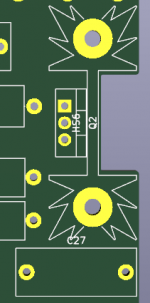
- Currently have MOSFET and heatsink placed on the edge of the board with a square notch for users looking to chassis mount the heatsink (see attached image)
- High Voltage circuit refined
- Trimpot now terminated to ground
- R20 is a user calculated resistor to set voltage adjustment range
- 10-15K 0.5W trimpot
- Supports center tapped transformers
- Center tap connects to J1 pin 2
- Omit D4, D5, C8, and C9
- Supports tube rectifiers
- Tube rectified DC connects to J5 pin 1
- Omit D4, D5, D7, D8, C8, C9, C15, and C16
- Supports CRC or CLC
- CRC via R6 (5W footprint), user calculated
- CLC by omitting R6 and connecting external choke to J5 pins 2 and 3
- Board ventilation holes for R6
- Changed all 1N4007/HER108G diodes to UF4007
- SF1200, 1N4007, BYV26E, SF4007 should all be valid substitutes
- Added adjustable time delay relay circuit for high voltage
- NE556 timer based
- Default is 30seconds, increase R4 and/or C12 to increase timer
- Relay is common footprint G2RL-2-DC5 DPDT
- There are many valid substitutes to choose from
- Relay protected with varistor across load
- LED D15 blinks every second with timer and turns solid once relay is armed
- Test point clips for regulated and unregulated voltages
** Working On **
- Board layout aiming for minimum size
- BOM write up
- links to mouser/digikey for parts
- part numbers for valid choices for filament LDO
Attachments
Looking very good BH!
My concern is it looks like the HV section only accepts a center tapped transformer? That will eliminate a lot of trafo options, including most Anteks.
My concern is it looks like the HV section only accepts a center tapped transformer? That will eliminate a lot of trafo options, including most Anteks.
Looking very good BH!
My concern is it looks like the HV section only accepts a center tapped transformer? That will eliminate a lot of trafo options, including most Anteks.
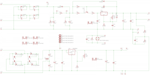
Thanks! The center tap just goes go ground like the original board (original schematic attached). I just moved the center tap connection to the center pin of the 3 pin terminal block for J1 on my schematic. Between the original board and my updated schematic, functionally no changes have occurred on the HV section until we reach the LM317 regulator and MOSFET.
Attachments
The timing LED is a nice touch, a bit of fancy added. You’ve packed in a bunch of upgrades/modifications from the original design. Keep it up!! Looking forward to the artwork 😉.
Yes Vunce , I have been working with BH on this, and the need to make it as versatile as possible leads to your question in post #52.
On the HV supply most builders I assume (me included) will use a single HVAC secondary winding connected to pins 1 and 3 on J1. Pin 2 is not used or connected.
If one wanted to use a CT sec winding, then omit 2 diodes D4 and D5, with their snubber caps, and wire to J1 as shown.
If using an offboard tube rectifier then omit the entire bridge rectifier components and wire the pos DC to J5 pin 1 and the neg to J1 pin 2.
I will also give options for the value of R20 in another post, to show a number of desired output DCV ranges when adjusting pot RV3 being either 10K or 15K in value.
BH is doing a great job on this board, the only issue so far is the supply problems and long lead times for many components.
Im still not solidly sold on floating 3-pin regulators, they can become unstable, and layout and component choice is very inportant. When they are working, pretty quiet and consistant, when they are not, a nightmare to tame!!
The timing LED is a nice touch, a bit of fancy added. You’ve packed in a bunch of upgrades/modifications from the original design. Keep it up!! Looking forward to the artwork 😉.
Thanks Vunce, hopefully it doesn't look like a Salvador Dali created PCB 😀
I note your comment denny, but I have had no problems with that type of circuit so far - and there are a lot of them out there.
no worries! I respect that completely.I note your comment denny, but I have had no problems with that type of circuit so far - and there are a lot of them out there.
Yeh, the 723 is a good regulator, but I think one of the issues is pcb size. If the pcb got too big then that would be an issue for builders as well.
Just on the LM723, when I was working the company would use hundreds of them in linear power supplies - but would only use the higher spec metal can version for reliability. Of course they were cheaper then and always available. That package is still available but goes for around $20 each these days.
Just on the LM723, when I was working the company would use hundreds of them in linear power supplies - but would only use the higher spec metal can version for reliability. Of course they were cheaper then and always available. That package is still available but goes for around $20 each these days.
- Home
- Amplifiers
- Power Supplies
- The Ultimate Tube Preamp Power Supply