Thanks bloqhed, for the HV delay using ESP circuit, you can use the 6.3VAC supply that will feed the filament regulator. he also has a delay circuit using a 555 timer IC that mutes the audio output at the amp. If using the HV delay than the main point is to use a suitably rated relay with contacts rated for 250VAC with both double pole contacts wired in series to switch the HV AC supply to the regulator. I have not seen Jan's circuit yet - but will have a look.
Yeh the trimpot is as I said, but normal practice is to have a fixed resistor between Vout and ADJ pin and the trimpot in the lower position with the wiper (pin 2) and pin 1 to GND. Or to be more safe a fixed resistor in place of the pot calculated for the exact filament voltage. In your circuit with 100 ohm resistor between Vout and ADJ, the bottom resistor would be 408 ohms based on the IC ref volts as being 1.240VDC, for a 6.3VDC supply and 916ohms for a 12.6VDC supply. Use the nearest 1% value = 407ohms and 910ohms.
All good with your comments on the CL-60 NTC.
Yeh as long as you use a common sized electro cap footprint and lead spacing, then some shopping around might have to be done on the caps.
When I looked at Mouser for the BUT11A it said it was obsolete, but your link shows in stock, the FET might be a better option here though.
The PR03's are good. What have you picked for the 5W resistor R4 - it is wrong on the BOM. Maybe this one: 279-ROX5SSJ1K0 at Mouser.
Keep up the good work, much appreciated.
Let me know what you think of Jan's circuit, I like that as it doesn't need to tap off the 6.3vac windings, makes for an easier time with PCB traces, also no relays, it uses a MOSFET for a switch.
Fixed resistors would be nice, but in order to keep with the original spec of being more versatile, eg: 2.5-12.6VDC @ 4.5A, we'll need to keep the pot in. I think a switchable array of resistors would be a bit much for a footprint. That said I am open to expanding upon this feature, unless I'm missing something there's a decent variety of tube filament voltages that could be powered by this hence the need for 2.5-12.6 and not strictly 6.3/12.6?
I've picked out a tentative MOSFET and redrawn the circuit according to ra7's helpful comments. Tentatively looking at STP11N65M2 as it's around the same price as that BUT11A, and seems to have good heat dissipation and low rdson. I'll be posting a v1.1 schematic with that soon. I've also swapped the original loop breaker circuit into a CL-60 and 22nf 300VAC+ Y2, changed large cap footprints to 22mm diameter, and changed the solder points to 2 or 3 terminal 5.08mm pitch terminal blocks.
For that 5W resistor, the original BOM says 100-220R or remove if using a choke, the schematic shows it as 1K. I have always interpreted this as the R in a CRC filter and could be sized anywhere from 0.1-whatever as long as users calculate proper resistor wattage for the amount of voltage drop desired across it. Overall I'm still working on cleaning up the BOM to PR03's, changed parts, etc.
I have had a look at Jan's HV delay circuit - both the original one in 2014 and the updated one in 2019. The big problem is the need for a pre programmed PIC controller IC. This comes as part of the DiyAudio store kit with the pcb and fets. A nice design though. Maybe one can program the chip themselves when I read the article from 2019 - do you know for sure on this?
I am OK with the pot to adjust the output voltage.
I would probably use a choke instead of R4, all good with the other mods.
I am OK with the pot to adjust the output voltage.
I would probably use a choke instead of R4, all good with the other mods.
You are right, I only glanced at the 2019 doc from Jan and didn't catch that you have to program the chip. Maybe the ESP design is ideal as it doesn't require anything over the top like that, I'm hoping to avoid relays for longevity.
Using a good quality relay will not be a problem, especially when using 2 contacts in series as per the ESP article.
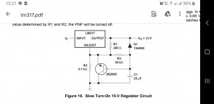
The ultimate circuit is the one that works with the minimum amount of components.NE555 is unbeatable for delaying anything.What's the reason to have an IC that has auto reset? That's just one more problem if PIC supply gets unstable .lm317 will always allow for the perfect fillament slow start with just 2 more components(a 10...22uf cap and a resistor)...but a cap multiplier is just good enough.
The word " ultimate" is used in excess to justify all sorts of expensive complications. If you're comming from a fix and repair background you know that the simplest solution is the best one too.
The word " ultimate" is used in excess to justify all sorts of expensive complications. If you're comming from a fix and repair background you know that the simplest solution is the best one too.

This project is sort of a ‘clone’ with modifications. The name “Ultimate…psu” comes from the original designer and should stay that way.
Keeping the HV delay circuit simple with minimal parts count is something I agree with.
The filament psu section works fine, no need to make changes there with added parts.
Keeping the HV delay circuit simple with minimal parts count is something I agree with.
The filament psu section works fine, no need to make changes there with added parts.
The ultimate circuit is the one that works with the minimum amount of components.NE555 is unbeatable for delaying anything.What's the reason to have an IC that has auto reset? That's just one more problem if PIC supply gets unstable .lm317 will always allow for the perfect fillament slow start with just 2 more components(a 10...22uf cap and a resistor)...but a cap multiplier is just good enough.
The word " ultimate" is used in excess to justify all sorts of expensive complications. If you're comming from a fix and repair background you know that the simplest solution is the best one too.
We aren't going with any programmable chips at this point, right now looking at a variation of Pete Millett's muting delay circuit. eg: a 555 timer to control a 250v relay with the contacts in series like Rod Elliott's circuit shows. I've drawn up Rod's but since it uses a 16dip CMOS timer, I feel it will have a larger footprint, and I think I can have a smaller footprint with a riff off Pete's circuit. Essentially the top half of the attached circuit as I don't think we need the footprint of the LED portion unless other people want me to include that. Where I am unsure is, can I tap off the rectified filament DC current that has ground elevated to 1/4 B+ voltage, and run the high voltage delay circuit with an elevated ground? That would save on components in the circuit.
What the hell do you need 2 x ne555 for?
If you chose dc fillament and /or slow start filtered , you shouldn't care about anything as long as you couple only the B+through relays and have different secondary windings for filament and HV supply.The fillament lifting is better done by connecting the fillament through 100k...10Megohm to 1/4 V B+
You can lift that fillament even if it's AC and the effect still works.In fact dc fillament doesn't completely solve the noise because that is in the picoampers range where no regulator really is noiseless, fillament lifting is much more potent.
What the hell do you need 2 x ne555 for?
If you chose dc fillament and /or slow start filtered , you shouldn't care about anything as long as you couple only the B+through relays and have different secondary windings for filament and HV supply.The fillament lifting is better done by connecting the fillament through 100k...10Megohm to 1/4 V B+
You can lift that fillament even if it's AC and the effect still works.In fact dc fillament doesn't completely solve the noise because that is in the picoampers range where no regulator really is noiseless, fillament lifting is much more potent.
As I said in my post, just the top half, which if you notice, only uses a single 555 timer. Per the schematic I attached as an example where I'm just using the top half as a starting point, you'll see that the bottom half with the second 555 is only if you wish to have an LED, which I do not. I believe I mentioned in my previous post that I was not interested in the LED portion of the example I posted. You're welcome to read up on that particular circuit on Pete Millet's website.
I think you should be alright with the delay circuit with elevated gnd at 1/4 B+, as long as you don't connect LV gnd to HV gnd anywhere. Otherwise you will need a separate supply.
Also I note the use of 2 relays with SPDT contacts, you only need 1 relay with DPDT contacts as far as I can see. Depends what the relay contacts are switching.
Also I note the use of 2 relays with SPDT contacts, you only need 1 relay with DPDT contacts as far as I can see. Depends what the relay contacts are switching.
I think you should be alright with the delay circuit with elevated gnd at 1/4 B+, as long as you don't connect LV gnd to HV gnd anywhere. Otherwise you will need a separate supply.
Also I note the use of 2 relays with SPDT contacts, you only need 1 relay with DPDT contacts as far as I can see. Depends what the relay contacts are switching.
Good to know on the ground thanks, one relay is the plan, Pete's schematic is originally tailored for signal output hence 2 relays, as you said, we only need one. 🙂
Good work, Bloqhed. Here is an interesting circuit - it counts mains cycles for a power on delay - no microprocessor
http://www.next.gr/circuits/Simple-B-delay-circuit-for-tube-power-amp-l38806.html
http://www.next.gr/circuits/Simple-B-delay-circuit-for-tube-power-amp-l38806.html
Good work, Bloqhed. Here is an interesting circuit - it counts mains cycles for a power on delay - no microprocessor
http://www.next.gr/circuits/Simple-B-delay-circuit-for-tube-power-amp-l38806.html
Thanks I will take a peek at this one.
Been a bit busy at work this week, but I've still made some good progress. I need to refine the high voltage regulation a little bit and I should have a new schematic to post then, hopefully in the next couple of days. In parallel to the schematic I'm also working on fine tuning things like resistor footprints to maximize available board space.
I would simply float a UA723, add a zener follower to power the chip, and You will have a cleaner B+ and better regulation for about the same price. expect at least 2uV noise level.Intro:
A user on diyaudio had a store on ebay where he sold some quite nice regulated filament boards, and some all in one high voltage / low voltage boards, I think some tube preamp boards too. This user does not appear to be active or selling them anymore. I've done some scouring on the internet and managed to locate the schematic, pictures of the boards original layout, track layout, BOM, etc. This board at it's base level is a high voltage circuit with a maida regulator, an LDO filament circuit with it's ground elevated to 1/4 of high the voltage, a jumper to get a wider low voltage span, and, a built in ground loop breaker, at the bottom of this post I have some snippets from the original listing.
Goal:
Many of us have a need for a quality linear tube power supply board, and they appear to be difficult to find, or lacking desired features. Why not make our own? I assume as the user posted all of the schematics, BOM, layout, tracks, etc, on their ebay page with the listing, we can assume this is a schematic that is open-source. So let's pick it up from there and design the Ultimate Open-Source Tube Preamp PSU. I think that this board should definitely have an added high voltage delay, and perhaps some other features I am not thinking of. Perhaps some keen eyes will identify ways the circuit can be improved upon.
I've drawn the schematic up in KiCad, assigned footprints based on the original BOM, and working on matching the original layout. Below are some notes I have taken for modifications I have made, things I don't quite understand, and things that I think should be added. All gerbers and schematics will be freely available for anyone to use, and if desired I can work on the KiCad project available for people as well.
Modifications Added:
Modifications Needed:
- Optional snubber circuit positions added to both heater and plate AC inputs
Questions and Thoughts:
- High voltage delay - can it be done without increasing the board footprint drastically?
Here's the current schematic;
- I'm unsure of why pin 1 of trim pots is not attached to anything
- The original boards loop breaker uses ESP's design (diode bridge, 10R/100nF), xrk971 uses thermistor/cap, is one better than the other?
- if keeping with ESP design, GBU diode bridge should be increased from 8A to 25A for maximum safety (I think)
- if going with xrk971's thermistor/cap style, what values?
- Original BOM calls for WIMA, Nichicon KW (filament), Nichicon KX (plate), are there better choices for this application?
- Is it worth mounting resistors vertically to save on board size?
View attachment 1081713
Note:
I only started poking around with KiCad a couple of months ago, and electronics/DIY audio only ~2 years ago, so bear with me when it comes to my ignorance 😀
****
Original Board Notes:
I created this PCB for a personal project. Originally I planned to buy the PS-1 designed by John Broskie. John designed the Aikido line stage and has some great power supplies. The PS-1 is a great power supply but it didn't have a few things I was looking for. I really wanted to get 6.3VDC regulated voltage out of 6.3VAC winding on my transformer and I wanted headroom for high current heater projects. I also wanted some options to use a choke with the high voltage. Those were deal-breakers for me and his boards couldn't give me what I needed. So I designed my own. I ended up with a great board and had plenty of extras made for fellow hobbyists.
High Voltage: 50-400VDC @ 200mA
Low Voltage: 2.5-12.6VDC @ 4.5A
Heater Circuit:
Regulated 6.3VDC from 6.3VAC winding with the use of schottky diodes and super low dropout regulator. Or 5VDC from 5VAC, etc. This isn’t possible with almost every power supply out there.
Voltage doubler jumper and trimpot adjustment. Allows for switching between 6.3V tubes and 12.6V tube without pulling out your soldering iron. Simply move the jumper and dial in the pot. A standard 6.3VAC transformer winding now allows the use of twice the tube choices. Go price a NOS 12SN7 vs a NOS 6SN7 and see how this board pays for itself.
Huge capacitance for ultra-low ripple. 45,000uF capacitance.
Full 4.5 amps of available heater current. High current components and heat management designed in. Large heat sink on LDO and heat sinks on all rectifying diodes. Remember you need 1.8X the DC current from your transformer. For example: to power 4 6SN7 tubes for a total of 2.4A, you need a theoretical bare minimum of 4.32A available from your transformer. A safer rule of thumb is 2.0X the DC current. If you're using the doubler, then current gets cut in half once more (darn that Ohms law).
Two sets of heater outputs.
High Voltage Circuit:
Regulated output using Maida circuit.
Huge capacitance for ultra-low ripple. 256uF capacitance.
Accepts multiple configurations. Full wave bridge, tube rectifier, or full wave center tap.
Allows for external choke filter (C-L-C) or 5W voltage dropping resistor (C-R-C).
Two sets of B+ outputs.
Additional Features:
1/4 B+ reference circuit built in. Elevates the heater ground to 1/4 of the B+ voltage. Provides for hum free power and cathode protection.
House ground isolation circuit built in. Chassis and House ground attach to the board for a hum free experience.
A jumper location is provided to ground directly through one of the mounting screws for the chassis ground. Or wire the chassis ground traditionally with the provided wire pad.
Designed for use with high end audio grade components (Wima MPK series, Nichicon KX and KW series, etc).
Small and compact. All this circuitry is smartly arranged on a 4" X 6.25" board.
Thick PCB with 2 ounce traces.
A BOM from Mouser is below. I used all high end components (Wima and Nichicon Audio caps, etc). Full schematic and board layout are above. If you're handy you can wire one up point to point with all the info in this add and skip the need to buy the PCB. Please know your skill level and knowledge of electronics before considering this PCB. If Mouser is out of something try DigiKey. You should be comfortable specifying substitutions. I do my best to keep the direct link BOM updated. Note main picture shows a slightly different revision but with exact same schematic.
Mouser direct link for Pre-Amp PS BOM
Here's what the original board looked like empty and stuffed.
View attachment 1081646
View attachment 1081649
View attachment 1081714
Post Edits:
- Aug 16, 2022
- Identified missing R14 in schematic, corrected and updated.
- Attached original schematic
- Added original BOM (note: original schematic parts don't necessarily match BOM, I designed the schematic around the original schematic but based parts and values off the BOM)
- Added zipped BOM with .xlsx and .pdf
I would simply float a UA723, add a zener follower to power the chip, and You will have a cleaner B+ and better regulation for about the same price. expect at least 2uV noise level.
I really like the sound of that excessively low noise level. But here the novice in me screams. Do you have any example schematics I can look at to get some ideas and understanding? I'm a learn by example type.
This is'nt a floating design but here is one Ive worked up in both Spice and breadboarded, it works great under no load and 10mA load. it may need some refinement, but not much I would think.I really like the sound of that excessively low noise level. But here the novice in me screams. Do you have any example schematics I can look at to get some ideas and understanding? I'm a learn by example type.
Attachments

I can give you a better schematic as well. Let Me know. ThanksThis is'nt a floating design but here is one Ive worked up in both Spice and breadboarded, it works great under no load and 10mA load. it may need some refinement, but not much I would think.
- Home
- Amplifiers
- Power Supplies
- The Ultimate Tube Preamp Power Supply