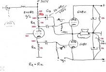
With this p.inverter configuration input VAS stage output can be inverted type , so this will allow to use single high gain AF pentode for VAS stage same is in original Futterman amp , 6AU6 ,EF86,EF94,... altogether with high GNFB to reduce amp output Z to minimum ,
high gain triode input VAS stage(ECC83) can be also used here but than with moderate GNFB .
high gain triode input VAS stage(ECC83) can be also used here but than with moderate GNFB .
try with from 4K7 to 10 K ,
the lower Rb the higher Cb have to be ,
but let`s say Rb=8K2 with Cb=47uF .
Thanks @banat - I see.
Well, I must confess that I'm not very fond of that 47µF if I think about a polypropylene one, even if the voltage can be reduced to 250V : it's rather a big unit and the space is counted in my compact chassis... 😱:
It's worth to test to see the result - I think an Hi-Fi Freak long-time pal is testing that solution in the meantime too, with a non-crossed Cathodyne output though. I'll call him back to know further about that.
I will probably have to de-cross my Cathodyne output to apply that recipe, with the inconvenience of loosing a linearity correction equivalent to a 6dB NFB loop due to the crossing, as shown below :

That said, the de-crossing will allow the installation of a NFB loop that would be impossible with crossing, unless you want a positive reaction that increase input sensivity but is detrimental to the linearity and bandwidth.
But if you de-cross and install a NFB loop, then its level must be over to 6dB to provide any advantage on the cross solution, with moreover an added loss of input sensivity of 30% (even if it's not so dramatical, though).
These are the conclusions I draw from my measurements of this morning.
The time to make choices and arbitrations is coming... 😉
So Wait and See... 🙂
A+!
No need for big polypropylene on Cb , ordinary but quality 450VDC rating electrolytic condenser will be OK , what is important is to find optimum Cb value by listening experiment,
if Cb value is to big than Bass spectrum will sound bloated , if Cb is to small bass spectrum will be insufficient ,
one more thing , to get stiffer and better defined gnd floating reference 0 point is good to insert one 1K/2-3W from power transformer CT to speaker (-) floating 0 reference point .
if Cb value is to big than Bass spectrum will sound bloated , if Cb is to small bass spectrum will be insufficient ,
one more thing , to get stiffer and better defined gnd floating reference 0 point is good to insert one 1K/2-3W from power transformer CT to speaker (-) floating 0 reference point .
Attachments
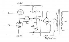
Scope the One K resistor to the Transformer CT, Measure current unbalance. Valuable information. I insert something like 10R into the rectifier return to the common as a habit. Good to know what the current pulses are & their magnitude.🙂
Good idea, Guys, but my PSU has no transformer CT, so current imbalance is not really possible, or at least very limited to the 12K shunt resistors 😀
I installed 3 sets of 6080 right out of the box without any control, plus some used ones, and made tube mixes : the imbalance is 115V +/-3V at max. 😎
Tomorrow, I'll redo some tests with the SRPP circuit, using a variable supply divider, in order to try to fine-tune the DC coupling which is more picky with the SRPP.
Maybe it will be unsatisfactory because of the unability to compensate enough gaps occuring in tube mismatching regarding the specs and the twin-triode. but I want to test it : well tuned, the SRPP showed the most linear and symmetric performance that I noted, so... 😉
I see @banat... This is another point that I do not like too much... if I can avoid any supplementary kind of cap, it's better IMHO. My Pal did not made his tests yet : I let him check that solution first and heard about his results ! 🙂
A+!
I installed 3 sets of 6080 right out of the box without any control, plus some used ones, and made tube mixes : the imbalance is 115V +/-3V at max. 😎
Tomorrow, I'll redo some tests with the SRPP circuit, using a variable supply divider, in order to try to fine-tune the DC coupling which is more picky with the SRPP.
Maybe it will be unsatisfactory because of the unability to compensate enough gaps occuring in tube mismatching regarding the specs and the twin-triode. but I want to test it : well tuned, the SRPP showed the most linear and symmetric performance that I noted, so... 😉
No need for big polypropylene on Cb , ordinary but quality 450VDC rating electrolytic condenser will be OK , what is important is to find optimum Cb value by listening experiment, if Cb value is to big than Bass spectrum will sound bloated , if Cb is to small bass spectrum will be insufficient.
I see @banat... This is another point that I do not like too much... if I can avoid any supplementary kind of cap, it's better IMHO. My Pal did not made his tests yet : I let him check that solution first and heard about his results ! 🙂
A+!
Last edited:
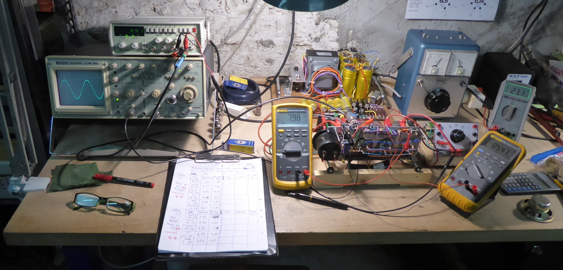
Tests with an adjustable divider to supply the input stage, in order to compensate mismatch and datasheet specs drift of 12AX7 : the solution proves to be efficient... 😎😎😎
I checked with 6 different tubes :
1 - 1.10/1.10 ECC83 unknown
2 - 1.0/1.0 12AX7 MESA
3 - 1.45/1.60 12AX7WA ECG
4 - 1.0/0.8 12AX7 Weak
5 - 1.9/1.0 12AX7 chepah
6 - 2.1/1.4 Sylvania NOS
The datasheet specifies 1.2/1.2mA
I also tested 2 12AU7 in the Cathodyne stage : 10/11 and 12/12 while the datasheet specifies 10.5/10.5mA. No noticeable changes noted.
The oscillograms below only shows the pictures for the tube 1, because there's no difference with the other tubes (except the 6) : the waveforms are strictly identical - once the divider balance made.
* Sinus 440Hz, onset of clipping, 13.32VRMS 16R, 13.32²/16=11WRMS output. Input signal is between 695mV and 722mVRMS.

* Triangle, same peak-to-peak amplitude as sine wave.
* Input and output simperimposed waveforms.
* Results with highly mismatched and over-spec'ed tube 6. The divider balance cannot completely correct the faulty tube. Input signal is 886mV.
Obviously, the tube 6 must be discarded for this application, but the 5 others could be compensated perfectly... It's better than I expected ! 🙂
The bandwidth is checked at <1Hz - 180Khz @-3dB at 10WRMS output 16R. 😎
OK, I stop here - I find those results enough satisfactory in regard of the simplicity of the circuit. 😉
A+!
I checked with 6 different tubes :
1 - 1.10/1.10 ECC83 unknown
2 - 1.0/1.0 12AX7 MESA
3 - 1.45/1.60 12AX7WA ECG
4 - 1.0/0.8 12AX7 Weak
5 - 1.9/1.0 12AX7 chepah
6 - 2.1/1.4 Sylvania NOS
The datasheet specifies 1.2/1.2mA
I also tested 2 12AU7 in the Cathodyne stage : 10/11 and 12/12 while the datasheet specifies 10.5/10.5mA. No noticeable changes noted.
The oscillograms below only shows the pictures for the tube 1, because there's no difference with the other tubes (except the 6) : the waveforms are strictly identical - once the divider balance made.
* Sinus 440Hz, onset of clipping, 13.32VRMS 16R, 13.32²/16=11WRMS output. Input signal is between 695mV and 722mVRMS.
* Triangle, same peak-to-peak amplitude as sine wave.
* Input and output simperimposed waveforms.
* Results with highly mismatched and over-spec'ed tube 6. The divider balance cannot completely correct the faulty tube. Input signal is 886mV.
Obviously, the tube 6 must be discarded for this application, but the 5 others could be compensated perfectly... It's better than I expected ! 🙂
The bandwidth is checked at <1Hz - 180Khz @-3dB at 10WRMS output 16R. 😎
OK, I stop here - I find those results enough satisfactory in regard of the simplicity of the circuit. 😉
A+!
BW is no problem in an amplifier with no OPT.
Damping Factor is an important factor to control the speaker.
Few speakers do much above 20 KHz. Heard only by cats, bats & dogs.🙂
Damping Factor is an important factor to control the speaker.
Few speakers do much above 20 KHz. Heard only by cats, bats & dogs.🙂
😕🙂😉 OK - it seems to work this time - so I repost the faulty message #147 ...
Tests with an adjustable divider to supply the input stage, in order to compensate mismatch and datasheet specs drift of 12AX7 : the solution proves to be efficient...
I checked with 6 different tubes :
1 - 1.10/1.10 ECC83 unknown
2 - 1.0/1.0 12AX7 MESA
3 - 1.45/1.60 12AX7WA ECG
4 - 1.0/0.8 12AX7 Weak
5 - 1.9/1.0 12AX7 chepah
6 - 2.1/1.4 Sylvania NOS
The datasheet specifies 1.2/1.2mA
I also tested 2 12AU7 in the Cathodyne stage : 10/11 and 12/12 while the datasheet specifies 10.5/10.5mA. No noticeable changes noted.
The oscillograms below only shows the pictures for the tube 1, because there's no difference with the other tubes (except the 6) : the waveforms are strictly identical - once the divider balance made.
* Sinus 440Hz, onset of clipping, 13.32VRMS 16R, 13.32²/16=11WRMS output. Input signal is between 695mV and 722mVRMS.

* Triangle, same peak-to-peak amplitude as sine wave.

* Input and output simperimposed waveforms.

* Results with highly mismatched and over-spec'ed tube 6. The divider balance cannot completely correct the faulty tube. Input signal is 886mV.

Obviously, the tube 6 must be discarded for this application, but the 5 others could be compensated perfectly... It's better than I expected !
The bandwidth is checked at <1Hz - 180Khz @-3dB at 10WRMS output 16R.
OK, I stop here - I find those results enough satisfactory in regard of the simplicity of the circuit.
A+!
Tests with an adjustable divider to supply the input stage, in order to compensate mismatch and datasheet specs drift of 12AX7 : the solution proves to be efficient...
I checked with 6 different tubes :
1 - 1.10/1.10 ECC83 unknown
2 - 1.0/1.0 12AX7 MESA
3 - 1.45/1.60 12AX7WA ECG
4 - 1.0/0.8 12AX7 Weak
5 - 1.9/1.0 12AX7 chepah
6 - 2.1/1.4 Sylvania NOS
The datasheet specifies 1.2/1.2mA
I also tested 2 12AU7 in the Cathodyne stage : 10/11 and 12/12 while the datasheet specifies 10.5/10.5mA. No noticeable changes noted.
The oscillograms below only shows the pictures for the tube 1, because there's no difference with the other tubes (except the 6) : the waveforms are strictly identical - once the divider balance made.
* Sinus 440Hz, onset of clipping, 13.32VRMS 16R, 13.32²/16=11WRMS output. Input signal is between 695mV and 722mVRMS.
* Triangle, same peak-to-peak amplitude as sine wave.
* Input and output simperimposed waveforms.
* Results with highly mismatched and over-spec'ed tube 6. The divider balance cannot completely correct the faulty tube. Input signal is 886mV.
Obviously, the tube 6 must be discarded for this application, but the 5 others could be compensated perfectly... It's better than I expected !
The bandwidth is checked at <1Hz - 180Khz @-3dB at 10WRMS output 16R.
OK, I stop here - I find those results enough satisfactory in regard of the simplicity of the circuit.
A+!
Last edited:
What does this C6 do? And why isn't there any capacitor across the other bias potentiometer?
Best regards!
Best regards!
Where does the clipping happen? Input, driver or output stage?
Good Question, @mbrennwa 😱 : I think it's the preamp section just before the power section, but I will check to confirm... 😉
A+!
What does this C6 do? And why isn't there any capacitor across the other bias potentiometer?
Best regards!
@Kay Pirinha : to which schematic do you refer ?
A+!
Where does the clipping happen? Input, driver or output stage?
Here's the answer :
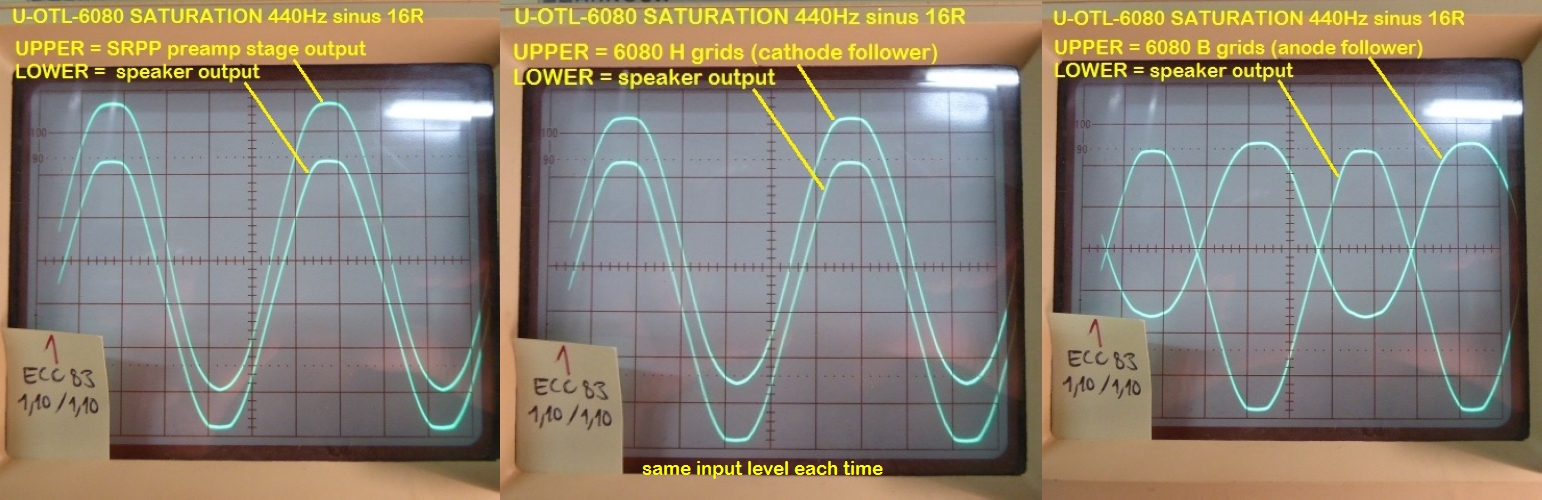
A part of the clipping occurs in the preamp stage, the other in the Cathodyne and output stage.
A+!
These curves all look clipped to me. Maybe use a triangle signal. Then slowly Rampen up the amplitude and check at the different spots.Here's the answer :
A part of the clipping occurs in the preamp stage, the other in the Cathodyne and output stage.
A+!
For me it's the output that clips first.
The grid of the lower 6080 looks ok, so must be the upper grid (relative to the cathode), cathodyne has same output on both sides.
For the upper 6080 the oscill shows grid+output wave and it is the clipping of the output you see.
Mona
The grid of the lower 6080 looks ok, so must be the upper grid (relative to the cathode), cathodyne has same output on both sides.
For the upper 6080 the oscill shows grid+output wave and it is the clipping of the output you see.
Mona
For me it's the output that clips first.
The grid of the lower 6080 looks ok, so must be the upper grid (relative to the cathode), cathodyne has same output on both sides.
For the upper 6080 the oscill shows grid+output wave and it is the clipping of the output you see.
Mona
Well, the final result is that the clipping at the output is symmetrical, and starts to be rounded (soft clipping) before reaching what is shown on the clipping pics.
It's a combined mix between input, Cathodyne and output stage clippings, showing the circuit reaches evenly its maximum possibilities, given its design simplicity and supply voltages available.
This Ultimate OTL 6080 amplifier will be built in two mono blocks, each in a 275x175x67mm Hammond aluminium die-cast chassis. So it will be a pair of compact OTL amps 😉... The same size and style as my Ultimate 300B below :
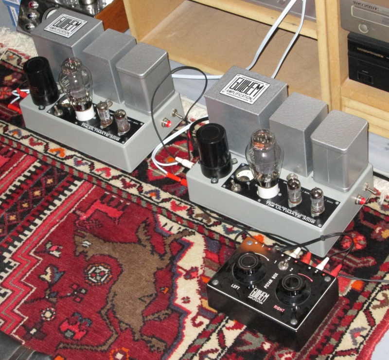
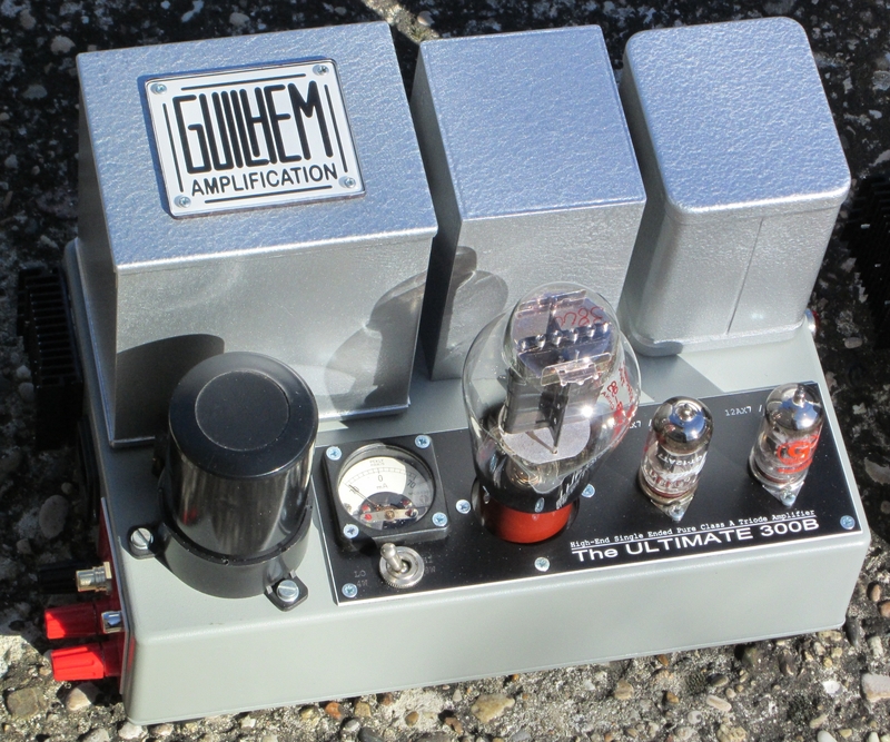
Orders are placed, so next step : building the units... It will take some time, I guess... 🙄
Wait and See !
A+!
Last edited:
Parts are arriving, step by step... 🙄
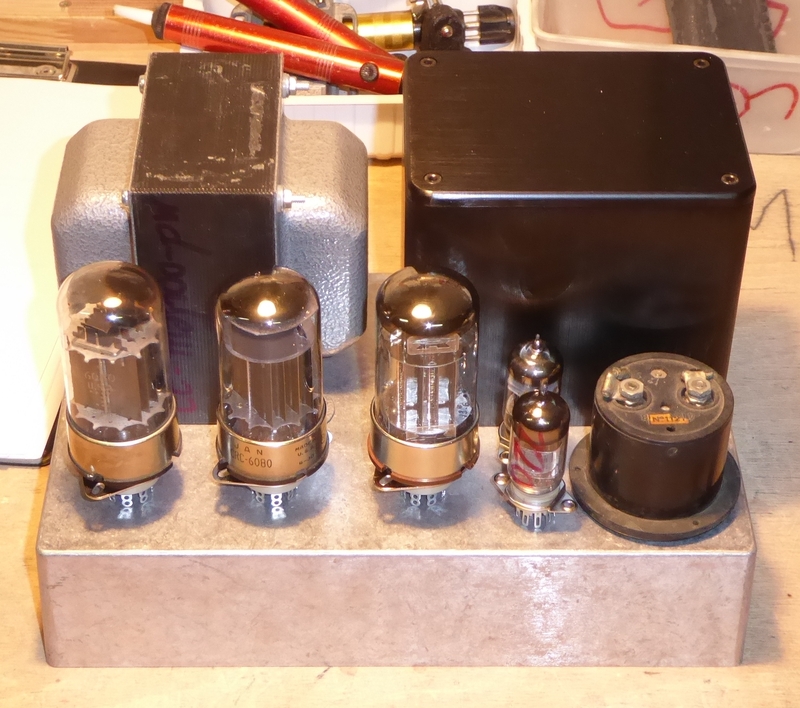
I should start the build in the days to come, it things goes well... 🙂
A+!
I should start the build in the days to come, it things goes well... 🙂
A+!
- Home
- Amplifiers
- Tubes / Valves
- The ultimate OTL6080