If you insist on having the speakers connected continuously to the amplifier then your speakers may have a problem when you turn on the amp , it may be correct that the impedance of the speakers will minimize the voltage of the tubes during start up , but don't forget that in the schematic we have parallel 6080 tubes , which mean low output impedance an high current so I suggest not to do that .
In case you put a delay relay then all the output voltage ( during start up )will appear in the input of the12ax7 because you don't have a DC path to ground only AC , I hope now you understand what I mean !!😀 . In general I would say that the whole design of the input stage is wrong , very low gain and high distortions .
Would you explain all this along with a matching schematic so I can understand, @Dimitris ? 😉
A+!
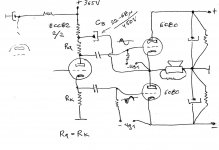
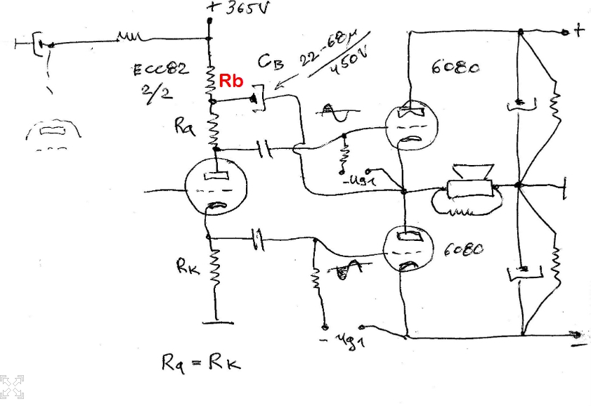
Instead of explaining , I will show you a simpler way to add some NFB , turn the schematic to normal Futterman topology , cause now you have inverted Futterman topology , ( the output impedance will increased a little , but don't worry ) and then add the two resistors like shown in the schematic below ! .
Attachments
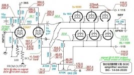
Instead of explaining , I will show you a simpler way to add some NFB , turn the schematic to normal Futterman topology , cause now you have inverted Futterman topology , ( the output impedance will increased a little , but don't worry ) and then add the two resistors like shown in the schematic below ! .
I experimented this before - you guess it 😉 - but the results are inferior, as shown by the oscillogram below :

No changes in the circuit except those stated on each picture, no NFB loop added.
Moreover, you did not answered to my previous request about your 2 statements 😕 :
Dimitris AR said:If you insist on having the speakers connected continuously to the amplifier then your speakers may have a problem when you turn on the amp , it may be correct that the impedance of the speakers will minimize the voltage of the tubes during start up , but don't forget that in the schematic we have parallel 6080 tubes , which mean low output impedance an high current so I suggest not to do that .
In case you put a delay relay then all the output voltage ( during start up )will appear in the input of the12ax7 because you don't have a DC path to ground only AC , I hope now you understand what I mean !! . In general I would say that the whole design of the input stage is wrong , very low gain and high distortions .
I don't know if @Ketje sees what your mean, but personally I don't... 😱
A+!
As long as you don't leave the speaker output open (1k is fine) I see no problem.I don't know if @Ketje sees what your mean, but personally I don't... 😱
And there is something wrong with the Dimitri mod.
There is positive DC feedback in the pre-stage.Not good for a stable zero-out.
Mona
Attachments
As long as you don't leave the speaker output open (1k is fine) I see no problem.
And there is something wrong with the Dimitri mod.
There is positive DC feedback in the pre-stage.Not good for a stable zero-out.
Mona
@Ketje : I made previously some tests without the 1K output resistor.
In open output circuit, the DCV reaches 19V offset about 4-5mn after powering the amp. With the 1K connected, the offset is lowered to 4.5VDC.
And then if you connect the speaker, in both case (= with or without the 1K), you heard a little scratch in the speaker without noticeable speaker cone movement, and the offset returns to zero mV.
I'm currently testing another input stage configurations : SRPP, Bootstrap... To see if I can reach better performance.
Wait and See !
A+!
I don't know if @Ketje sees what your mean, but personally I don't... 😱
A+!
You have to read a little bit more theory to understand what I mean !! and Ketje too ( I am talking about the input stage designed by Ketje ) .
@Ketje : I made previously some tests without the 1K output resistor.
In open output circuit, the DCV reaches 19V offset about 4-5mn after powering the amp. With the 1K connected, the offset is lowered to 4.5VDC.
A+!
19 V DC offset OMG !!! That's what happens when you have a floating power supply .
19 V DC offset OMG !!! That's what happens when you have a floating power supply .
Yes, if only there was an electrical component that would block DC but allow the passage of AC. Hmm...

haha , if you do not know it I can inform you 😀 .Yes, if only there was an electrical component that would block DC but allow the passage of AC. Hmm...
In my OTL inverted Futterman topology , I use a non floating power supply .
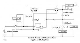
Universal Full Wave PS for OTL Amplfiers
Any OTL cct requires quite a myriad of Power Supplies of different voltages, often isolated from each other. So for anyone starting an OTL project here is a PS concept that would fill most requirements. And cause fewer headaches.😱
A double primary/double secondary, 117V/234V, 50/60 Hz toroid such as one of the Hammond 182 could be used. That way full wave rectification both for the power tubes & their drivers is possible. The two PS are isolated from each other.🙂
Attachments
You have to read a little bit more theory to understand what I mean !! and Ketje too ( I am talking about the input stage designed by Ketje ) .
I hate that form of dogmatism and lack of modesty of so-called "experts"...
Thank you @Brice, @jhstewart9 and @Ketje for your help and suggestions. 😉😎
I experimented today on another preamp stage - very simple design - that I used several times in the past and seems here to be able to improve the performance of the prototype, but it has to be confirmed :


A+!
The 20K is very good. Hard to do that with a classic design.
Yes, the performance is honourable, giving the simplicity of the circuit for an OTL, and for half of its maximum power output capability.
I'm still testing the SRPP circuit vs. the triode // circuit, in order to determine their respective pros and cons here in my prototype, because none of both prove to be undoubtedly or indisputably superior to the other at the first glance...
- dynamic offset stability to fortes.
- visible distortion vs the input signal.
- tube weakness or mismatchnig effect.
- performances in bandwith, sensivity and output power.
I also tested an ECC83 Bootstrap circuit, but it did not wanted to work with the preamp supply voltages available in my prototype.
Wait and See...
A+!
Here is the comparison between the SRPP and TRIODE // preamp circuit (click and zoom for full picture 😉 ) :

The gaps are underlined in yellow. Looking to the waveforms, the difference between the 2 circcuits is not very conclusive...
So I made a tube testing data collection to see what would be the influence of preamp tube weakness, excess and mismatching. I checked for each test (24 total) @ 500mVRMS sinus 440Hz :
- the signal output of the amp on 16R load.
- the cathodyne splitter direct coupling bias variation.
Verdict :
- the SRPP is a bit more linear if the preamp tube (12AX7) is well matched and in the specs (1.2mA per triode).
- The TRIODE // stays more linear with unmatched, excessive or weak tubes.
This is explained by the fact that the SRPP is serial DC operation and so allow no compensation of upper and lower triode current mismatching regarding the direct coupling to the Cathodyne.
Conversely, the TRIODE // allow each triode current to be possibly compensated by the other, because the plate resistors see the sum of both currents. So the direct bias variation to the Cathodyne is trherefore reduced.
In one word : TRIODE // introduces less imbalance with unmatched triodes than the SRPP, and finally offers a more consistent performance with random preamp tubes. The SRPP is more picky about tube matching to operate as best.
From the values I collected, the mismatching effect is reduced by 33% with the TRIODE // vs the SRPP. So I'm tempted to go for the TRIODE // preamp, then... 🙄
A+!
Last edited:
Did you ever try anode bootstrap cathodyne phase inverter for SEPP OPS ?
Yes, @banat - thanks for the reminder 😉
This interesting method you suggest is used on several OTL circuits (notably japanese) and I did not tested it yet...
But I will do, since it is a simple solution, and I want my circuit to stay as simple as compact as possible : it's the specification book I fixed.
The bootstrap I tested was different, or more standard if I can say so : it used a supplementary triode section in cathode follower to drive the Cathodyne.
It was unsuccessful because my supply voltages are too low for that kind of circuit.
A+!
By the way, @banat :
How much would you put for Rb here ? I saw values goind from 1K to 10K...
A+!
How much would you put for Rb here ? I saw values goind from 1K to 10K...
A+!
- Home
- Amplifiers
- Tubes / Valves
- The ultimate OTL6080