I'm not sure if there's going to be a meaningful difference between LME49713+LME49600 and LME49990+LME49600. I have my eval channel for the 49990 up and running. Parts for the 49710 and 49713 channels to A/B the 49990 against arrived yesterday but I haven't soldered them up yet---LME49720+LME49600 is extensively characterized in National Semiconductor's Application Note AN-1768 and I would not expect a 49710 to be much different. Math says there are diminishing returns above the 497x0's 55MHz typ GBP and that 20V/us is plenty of slew (with current limiting at 330mA full swing into six ohms within a single sample at 192kS/s is 768mV/us), so I expect minimal advantage to 49990 over 497x0 and equivalent performance between the 49990 and 49713 as with typical feedback resistors the 49713 winds up with about the same GBP as the 49990. Should have initial experimental findings in a week or two and more details around mid-December.
There'll be some variation in where 49600s current limit, but I'm getting a third of a watt peak into the Neo3s and around two thirds into the Neo10s and 18SWS1100s. Enough to get the total system output to about 90dB peak which, as I rarely listen above 80dB peak, is sufficient for my needs. Similar results should be possible with the BUF634. It's somewhat difficult to work with, but the OPA2677 is a cool little part that's interesting to consider as well. More practical is the LMH6321, which is decently linear even when operated outside of a composite amp and will push 700mA if suitably configured. See here for higher power options, though I suspect bridged 49713s or 49990s would outperform a 49724 and post 52 in this thread suggests its best to front a 49811 with as much attenuation is compatible with power requirements to deepen the bit depth the DACs (for 100W into 8 ohms I'd stick a 497x0 or 49722 with ~22dB attenuation in front of a 49811 operating at its minimum 26dB gain for stability---a composite amplifier works as well, though compensation for stability and knocking down the feedback voltage so as not to blow the op amp gets a bit tricky).
Oh, I forgot to link Craig's Neo3 waveguide in my previous post.
Last edited:
twest820,
Thanks for the detailed response! From reading your posts, you seem to be very educated in the workings of dipole alignments. As a result, you may be particularly well suited to answer this question that has had me wondering.
For a moment, lets assume we live in an ideal world. Loudspeakers behave according to the point source model and their diaphragms are perfectly rigid. Often, drivers are placed as near to each other as physically possible in order to minimize destructive interference. For baffled dipoles, the surface between the drivers is continuous. In order for the front and rear wavefronts from a given driver to interact in the vertical domain, they must traverse the full baffle height. For the lower driver, this would mean that the wavefront would have to pass over the upper driver before ultimately reaching the baffle edge. However, let us assume that no baffles are used. StigErik's loudspeakers are a good example. The surface between the two drivers is not continuous. Let us assume it would be possible for one to pass a finger from the front of the cone to the rear of the cone. In such a case, what would we define the path length to be in the vertical domain for the lower driver? I believe we can model a dipole as a point source surrounded by a ring radiator. Obviously the point source would be at the center of the driver, but would the ring radiator be the basket edge of the lower driver (~circular shape) or would it be the basket edge of the lower and upper drivers (~oval shape)?
Thanks,
Thadman
I suspect it will depend upon the width of the discontinuity with respect to wavelength. If we took the discontinuity as a limit and allowed it to approach an infinitesmally small distance, I believe it would present a resistance. The example that Dr. Geddes previously used with regards to a small hole in a hearing aid comes to mind. However, I am not sure if this would be the case.
Thadman,
assuming a point source will give you wrong results from the start. And as you already mentioned - small gaps between separate baffles don`t make the neighbouring baffle useless, but only "lossy". How lossy, would depend on the wavelength involved.
That said, in your example the "ring radiator" would roughly take the oval shape.
I have looked into the differences between point- and non-point sources in a small pdf. Download below the red text.
Rudolf
Thadman,
assuming a point source will give you wrong results from the start. And as you already mentioned - small gaps between separate baffles don`t make the neighbouring baffle useless, but only "lossy". How lossy, would depend on the wavelength involved.
That said, in your example the "ring radiator" would roughly take the oval shape.
I have looked into the differences between point- and non-point sources in a small pdf. Download below the red text.
Rudolf
Thanks😀
How lossy, would depend on the wavelength involved.
Rudolf
Could we generally assume the wavefront passes over the discontinuity if the discontinuity/wavelength < 1/6 (ie < 60* of the wave)?
No science, just gut feeling:
If the gap is 1/2 wavelength or larger, I would say "Forget about the other shore. Sound will be completely drowned in between".
If the gap is 1/10 or less, "Not worth to mention. Just jump".
Rudolf
If the gap is 1/2 wavelength or larger, I would say "Forget about the other shore. Sound will be completely drowned in between".
If the gap is 1/10 or less, "Not worth to mention. Just jump".
Rudolf
Last edited:
Twest820, or anyone else for that matter
I am waitng for my Dipole15's Neo10&3 to arrive so I can get started. While I'm waiting I have been looking around for amp modules to drive them in the long term. I have no real idea what sort of wattage I should be looking for. I was thinking for 50+50+120RMS, but hey, thats just an uneducated guess.
Can you give me your thought's on what would be a good ballpark figure. I dont tend to listern to my music very loud, but I guess it would be best to have some headroom for those rare occasions.
50+50 for the mid and tweeter should be more than enough. I have 60+60W on my OB system, and I can reach 120 dB peak with music without clipping the mid and tweeter amps. The efficiency of planar drivers you have there is pretty decent. The main challenge is the woofer, because of the EQ you'll need, and that increased the required power. You might want a little more than 120W.
It all depends on what not very loud means. For some people that's maybe 60dB peak, for others it's 100dB, so you'll probably want to get more specific. What I did was to measure my various listening levels with an oscilloscope, throw in some margin in case I move to a place with a larger listening space, end up switching to somewhat less efficient drivers, or move crossovers around, and choose a power channel design to suit. Main thing is to be careful to get good resolution of peaks when establishing the envelope the amp needs to serve.
With the current 200 and 1.7kHz crosses, peak levels on my Neo10s and 18SWS1100s are roughly equal and the Neo3's about 6dB down. My typical listening level is around 1 to 5mW RMS per speaker depending on the bass content of the piece---something like an order of magnitude increase from the 200uW of my box speaker days despite a 6dB increase in driver efficiency when moving from the boxes to dipole. But hey, nude dipoles aren't exactly efficient so I've got an average system efficiency in the mid-80s. Personally I'm OK with that as I've sized down the supply rails and chosen options which result in relatively low quiescent current draw by power amp standards---at my typical levels about two thirds of power consumption is quiescent draw---so I should end up dissipating a fairly green 2.5W per speaker. For comparison my previous amps were class A to 8W with 60V rails, or around 375W per speaker when triamping. 😱
As an update to the sand options listed or linked in post 81 I've completed the 49710+49600 and 49713+49600. Within the SEO (single ended op amp) space, I would suggest the 49713. Unless you require enough input impedance to make the 49990 a better choice. 😛
More neo10 and Neo3 fun.....just bought one of these to use as a center channel. Can't beat the price plus free shipping!
BG Radia Z-62 High Performance 200w Loudspeaker with Neo10 and Neo3 planar panels - Cherry | AV-Express
I will be modding with better damping like Bonded Logic on the inside, but seems like a steal giving the clearance price. Curious so see how the coaxial mounting thing works.
BG Radia Z-62 High Performance 200w Loudspeaker with Neo10 and Neo3 planar panels - Cherry | AV-Express
I will be modding with better damping like Bonded Logic on the inside, but seems like a steal giving the clearance price. Curious so see how the coaxial mounting thing works.
Attachments
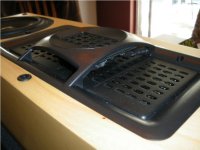
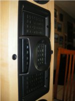
I've been curious about BG's coax approximation for some time as the arrangement's a bit unusual. I'm inclined to think of it as a compact MTM but it's not immediately obvious to me how much sticking Neo3 in front of the Neo10 tends to widen the Neo10's horizontal dispersion---measurements on this should be interesting. The back cup's left on the Neo3?
I've been curious about BG's coax approximation for some time as the arrangement's a bit unusual. I'm inclined to think of it as a compact MTM but it's not immediately obvious to me how much sticking Neo3 in front of the Neo10 tends to widen the Neo10's horizontal dispersion---measurements on this should be interesting. The back cup's left on the Neo3?
Yes, back cup is on Neo3 and then there is a thin sheet of something soft btw its back and the front of the Neo10. Horizontal dispersion is next to nill as expected. Looks like my seat in the middle is it....everyone else be damned.
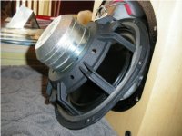
Sounds pretty decent so far. Bass is a little tubby, but I will be filtering out below 80Hz anyway, so no problem.
I think the coax arrangement mounted vertical with a nice woofer next to it would be sweet.
Greg
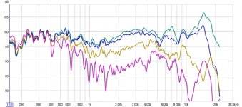
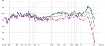
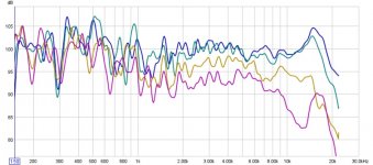
Neo10 directivity's shot. Ouch. I was hoping for better.
What does that mean, mine have just arrived.
Do the Neo10 etc have "Thiele / Small Parameters" or is that all out the door with this type of driver?
It means I'm disappointed in the performance of BG's coax module.
Thiele-Small parameters are conceptually valid for just about any dirver---I'm not quite sure how to think about say, Sd and xmax, for a plasma or flame tweeter but one can still compute an equivalent Vd. But for a moving membrane (electrostats, magnetostates) or cone/dome (pretty much everything else) the concepts are easy to apply. BG's magnetostats have very low Qms so Thiele-Small measurement procedure's difficult to apply, however---if you check Zaph's blog you'll see he remarks he didn't extract TS parameters from the Neo10 due to the lack of a clear impedance shift.
Thiele-Small parameters are conceptually valid for just about any dirver---I'm not quite sure how to think about say, Sd and xmax, for a plasma or flame tweeter but one can still compute an equivalent Vd. But for a moving membrane (electrostats, magnetostates) or cone/dome (pretty much everything else) the concepts are easy to apply. BG's magnetostats have very low Qms so Thiele-Small measurement procedure's difficult to apply, however---if you check Zaph's blog you'll see he remarks he didn't extract TS parameters from the Neo10 due to the lack of a clear impedance shift.
- Status
- Not open for further replies.
- Home
- Loudspeakers
- Multi-Way
- the three way nude swinging dipole thread