More
There is a lot more going on here than just a swinging pendulum which would only be the case if you had an ideally rigid structure to replace the cords or could some how attach them to the vertical center of mass of the driver. Even in this case, their own mass and very flexible nature could still allow whipping. Especially with such a light driver as the Neo3 which places very little tension on the cord. The attachment point is not at the vertical center of mass so the slight tension that is on the top of the driver will cause it to tend to rotate about this center axis which will whip the cords. The little Neo3 is pretty much free to jump around any way it wants after this. Some of the motion involved will mimic a weight on a spring in which case adding mass will lower the frequency and require more energy to get started in the first place.I guess you should dig deeper into swings 🙂
1. a swing is *meant* to suspend the driver like in outer space - meaning - this would be the ideal case to aim for.
2. there *must* be what you call "vibrational behavior" - this is part and parcel of 100% impulse cancellation with swings - these movements are *not* resonance - its a perfectly time aligned counter movement with no phase shift ringing or decay
3. there is no such thing as a resonance except the pendulum resonance
4. there is no such thing as a frequency down shift with added mass for pendulums
5. adding mass to the chassis affects the impulse cancellation movement of the chassis with respect to the diaphragm, yes, but this mass ratio usually is already way good enough - even for lightweight chassis as the NEO's
😉
Michael
There is a lot more going on here than just a swinging pendulum which would only be the case if you had an ideally rigid structure to replace the cords or could some how attach them to the vertical center of mass of the driver. Even in this case, their own mass and very flexible nature could still allow whipping. Especially with such a light driver as the Neo3 which places very little tension on the cord. The attachment point is not at the vertical center of mass so the slight tension that is on the top of the driver will cause it to tend to rotate about this center axis which will whip the cords. The little Neo3 is pretty much free to jump around any way it wants after this. Some of the motion involved will mimic a weight on a spring in which case adding mass will lower the frequency and require more energy to get started in the first place.
Rigid structures are no requirement for perfect swings.
First hand, are we - or are you - talking about speaker movement perpendicular to the suspension ???
In this case I do not see the points you make...
The tension on the cord (weight of the driver) has nothing to do with a *resonance* measured.
If suspension is more complex - as may be the case here - we would have to investigate first if its basically 2D or 3D.
In case of 3D suspension your points *may* come into play - most simple solution is to avoid 3D suspension as good as it gets - meaning - keeping either all cords and wires in one plane - or bring them together in one "pivot" - or when working with multiple "pivots" keep "pivots" in one (vertical) plane - or, or...
*if* preferring 3D suspension for one reason or another: keep 3D suspension planes in parallel - or, or ....
May ways to do it right - as can be seen, no need to generate resonance ...
😉
Michael
Michael
Last edited:
Agree; you might notice I built a nude first. 😛 But dipole waveguides are interesting on things like the Neos for directivity purposes and it's not clear to me symmetry cancellation of diffraction holds for cone woofers. Also interesting to explore baffle tradeoffs other than the ease of construction favored by flat, U, and H baffles. Bunch of research topics which may or may not prove to have something useful behind them.you pretty quick get into horn territory - with all the fuss of pro and con and the never ending discussions connected to it
This is into a 3-6 ohm dummy load or real driver in about the same range so the additional load of the Saffire's line ins should be negligible. I did the oscope measurements with the Saffire attached.Maybe difference between sound card and osci measurement is related to the huge difference in input impedance?
Tried zooming in dB but not in frequency. Will check on that next time I'm doing IMD; this is with 32k point FFTs so I'd expect the 1.5Hz resolution to clearly resolve the tones.
Something that I always do when designing a system, is at some point when I think that I am liking the basic crossover points and general relative levels, I will solo each driver to hear exactly what it is doing. I've been keeping the crossover point on my design btw 2.5 - 3KHz. Well, when listening to just the mids and Raal together today, on some vocals, I was hearing some distortion. I had the music quite loud, so I assumed that it was the lower range of the Neo10, so I moved the lower crossover point from 300hz up to 400hz. This did not help. I then solo'd just the Neo10 and no problem. Solo'd the Raal and there it was! Wasn't liking the 2.5Khz. All slopes are 24dB/oct. ended up all the way up to 4KHz and all was good. Neo10 sound just fine that high. Actually, they sound great, giving a little more umph and thwack to snare drums and mid heavy transient sounds. I do NOT want to see what this will do my polar response, but hey, something has to give with priorities and tradeoffs.
To bring this back around to your own project, I would suggest you try listening to just the Neo3. You might find that it gets a little harsh due to your lower xover point. Try closer to 3-4KHZ. You might be pleasantly suprised.
Greg
To bring this back around to your own project, I would suggest you try listening to just the Neo3. You might find that it gets a little harsh due to your lower xover point. Try closer to 3-4KHZ. You might be pleasantly suprised.
Greg
Good point.
I did that solo driver listening tests several times before but not recently. Very interesting indeed.
I did that solo driver listening tests several times before but not recently. Very interesting indeed.
No need to keep it tied to my build; this thread's intended to be more general than that. If you're driving the Neo3 hard a high cross is probably needed to clear the distortion spike around 2kHz---see the blue curve in the Neo3 data in post 1 of this thread. Does this also show up in your measurements? My typical levels with my 1.7kHz Neo3 to Neo10 cross are 5-10uW RMS and 500uW peak on the Neo3 (uW is not a typo; it's what I get from TrueRTA after calibration). That's below the green curve in the same figure, so for me the Neo3's not excursion limited until comfortably below 1kHz. A 1.7kHz LR6 cross clears that easily; in a previous iteration of this system I crossed the Neo3s at 1.6kHz LR6. I've crossed the Neo3s as low as 1.2kHz but found the results from 1.5kHz and below unsatisfying; need to go back and revisit them with more attention on phase matching at the cross and IMD as the THD data suggests 1.4 or 1.5kHz should be viable.Try closer to 3-4KHz.
Listening to individual drivers is quite helpful in my experience. I do it often, both with the Saffire's output mutes or by sticking my ear next to one of the drivers. One of the things I like about digital crossover and EQ is the ease of auditioning and measuring different configurations. While I personally don't care for the directive sound, my experience is the Neo10 makes an excellent full ranger and I prefer the Neo10s by themselves to a high cross to Neo3s. I find the vertical directivity glitch between the 10 and 3 annoying with crosses from 2kHz up and noticeable at 1.8kHz. 3kHz+ is a non-starter for me, but then directivity is the dominant speaker design criteria for me---for a lot of folks it's volume. So where 3kHz is what's needed to satisfy their requirements 1.7kHz works for me and I may eventually lower the crossover. (I wanted to spend some time getting used to 1.7kHz first and, as I'm currently fussing with power amps, the system's undergoing a lot of changes around which amp is handling which driver. I'm reluctant to complicate my subjective impressions of the amps by changing the crossover and EQ at the same time.)
See posts 1 and 20 in this thread. Any Neo10 front/rear asymmetry from the Neo3 cable is below measurement noise so I expect equally good matching once I get around to vertical polars. My avatar should give you some ideas about knocking the back cup off the Neo3W, though I believe some folks take them off with knives or chisels. You could probably also get some without back cup from Madisound since they're sold that way in the Nao Note driver set.
I was reading through Zaph Audio site re the Neo3PDR & he had this to say " Note: these were tested with the rear chamber in place. Later, with a different pair, I also tested with the chamber removed. The tweeter was far too overdamped in that case, and I recommend leaving the rear chamber installed." ?
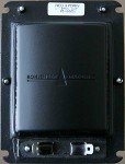
I the attached photo the Neo3 already has holes in the back? is this a mod or can you buy them like that? I assume not otherwise why would you be modifiing them? the second photo is I assume the standard back piece?
Why do you use the W rather than the PDRW
It is hard to see what's going on in your avatar, are you milling slots in the back?
Attachments
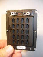
Removing the back cup exposes the punched plate---all the Neos are built with a more or less identical pair steel shells riveted together. I milled the backs off mine. Or, more accurately, milled the short side and about halfway down the long side before the flutes on the end mill popped the rest of the back cup off. Works great; didn't even need a finishing pass to clean things up. Most folks use rather less tooling for this, but I happen to have a vertical mill so it was more convenient than the other options
See my previous remarks about contacting Madisound if you want ones without backs. Post 3 has the EQ needed to get the Neo3W dipole peaks and dips flat.
I've not seen sufficiently detailed characterization of the PDRW to make a fully informed design choice between it and the W. The main difference is the PDRW has foam on the sides to narrow the effective radiating width with increasing frequency. This produces more consistent horizontal directivity at the expense of a greater disparity between horizontal and vertical directivity. Since I have strong preferences for consistent directivity on all axii I opted for the W. There's also some evidence the W may be slightly better behaved off axis than the PDRW but I've not seen anything conclusive. I can't comment further on the PDRW as I haven't tested any, but I think both cuibono and saurav's builds are using the PDRW.
Only if you want to separate the shells and get access to the bar magnets and membrane. I'm not sure when you'd ever want to do that, except taking apart a dead Neo to satisfy curiosity. The photos in DQ828's post are pretty clear about where the back cup, rivets, and holes are.Drilling through the rivets?
I switched to the non-PDR and sold the PDR versions. I've now been considering buying a PDR pair again and trying both side-by-side, instead of going by memory / charts. The non-PDR has less of an on-axis null, but it does drop off off-axis pretty quickly. So the "cross-fire" toe-in configuration doesn't really work, and I have them pointed almost at my head. They sound pretty good that way, and I don't really mind that the soundstage shifts if I move to the sides.I think both cuibono and saurav's builds are using the PDRW.
lol
The 2nd attached photo doesn't enlarge. I thought there's flange around the cup and is held by the rivets 😛
The 2nd attached photo doesn't enlarge. I thought there's flange around the cup and is held by the rivets 😛
No need to keep it tied to my build; this thread's intended to be more general than that. If you're driving the Neo3 hard a high cross is probably needed to clear the distortion spike around 2kHz---see the blue curve in the Neo3 data in post 1 of this thread. Does this also show up in your measurements? My typical levels with my 1.7kHz Neo3 to Neo10 cross are 5-10uW RMS and 500uW peak on the Neo3 (uW is not a typo; it's what I get from TrueRTA after calibration). That's below the green curve in the same figure, so for me the Neo3's not excursion limited until comfortably below 1kHz. A 1.7kHz LR6 cross clears that easily; in a previous iteration of this system I crossed the Neo3s at 1.6kHz LR6. I've crossed the Neo3s as low as 1.2kHz but found the results from 1.5kHz and below unsatisfying; need to go back and revisit them with more attention on phase matching at the cross and IMD as the THD data suggests 1.4 or 1.5kHz should be viable.
Listening to individual drivers is quite helpful in my experience. I do it often, both with the Saffire's output mutes or by sticking my ear next to one of the drivers. One of the things I like about digital crossover and EQ is the ease of auditioning and measuring different configurations. While I personally don't care for the directive sound, my experience is the Neo10 makes an excellent full ranger and I prefer the Neo10s by themselves to a high cross to Neo3s. I find the vertical directivity glitch between the 10 and 3 annoying with crosses from 2kHz up and noticeable at 1.8kHz. 3kHz+ is a non-starter for me, but then directivity is the dominant speaker design criteria for me---for a lot of folks it's volume. So where 3kHz is what's needed to satisfy their requirements 1.7kHz works for me and I may eventually lower the crossover. (I wanted to spend some time getting used to 1.7kHz first and, as I'm currently fussing with power amps, the system's undergoing a lot of changes around which amp is handling which driver. I'm reluctant to complicate my subjective impressions of the amps by changing the crossover and EQ at the same time.)
Interesting info here. I am moving away from better directivity I think....not sure yet, but something has got to give with this combo of drivers I've got. I don't have any Neo3 around, so I can't really help out there and it sounds like your power levels are considerably lower than mine. Mind you, I don't listen like that all the time, but it needs to be there and be CLEAN when I do wanna rock out. Average levels when I heard the straining of the Raal were around 85 dB SPL with peaks 10-15 dB higher with good, non-overcompressed material.
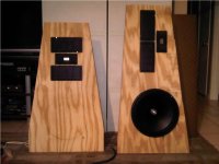
Also thinking about filtering the Dipole 15s below 50Hz and adding a pair of Rythmik Audio 15" servo subs along each wall behind the baffles. Not that the Dipoles really have any problems at anything less than VERY loud levels, but hey, I like my headroom. This is to be my own personal "BEST", so go big or go home.
Below is version 2.0. My attempt to control the side wall reflections more BEFORE adding acoustic panels. If I could afford more Neo10, I would make a virtual coax to surround the Raal. That would be sweet! If I ended liking some smaller cone drivers, this was my original intention. To kind of create a large oval around the Raal. Inspired by the Legacy audio Whisper and Helix models.
Greg
Attachments
Last edited:
Oh no, PartsExpress has the Neo10 for sale now too and with my discount they are much cheaper. Having bad thoughts about getting more to make that square I was talking about. Sheeeet!
Greg
Greg
Have you seen this:
http://www.diyaudio.com/forums/multi-way/90804-large-midrange-ob-scott-g-40.html#post1953221
😀
It's slightly different from your idea, but I guess something in common.
http://www.diyaudio.com/forums/multi-way/90804-large-midrange-ob-scott-g-40.html#post1953221
😀
It's slightly different from your idea, but I guess something in common.
Have you seen this:
http://www.diyaudio.com/forums/multi-way/90804-large-midrange-ob-scott-g-40.html#post1953221
😀
It's slightly different from your idea, but I guess something in common.
Yes I have. Very impressive. Thx.
Greg
Oh, sorry, my bad. Distortion knee on the Raals in your measurements is 2kHz so basically the same reasoning ends up applying for 140-15 crossovers though. 😛 The Neo3 has more low end grunt than any ribbon I know of; not surprising given its larger Sd.I don't have any Neo3 around, so I can't really help out there and it sounds like your power levels are considerably lower than mine.
No change with frequency zooming as well as dB zooming. TrueRTA shows a flat frequency response but I only have the one octave resolution demo so that's not very useful.Had no such issues - have you tried to zoom in to see if its a display problem?
I get the same 100% CPU problem with ARTA as with RMAA, so no love there either. I can record a .wav in Audacity and FFT it in Matlab, but that's starting to get a bit silly.
twest820,
thank you for sharing your findings with the community! I have been fascinated with the Neo10s for a while, however $150/each was a bit too much for me to justify being a guinea pig. It's refreshing to know they sound as good as the measurements suggest.
I'm interested in assembling a system similar to yours. However, my SPL requirements are much higher. I'm a fan of classical music and 90dB peaks just won't do it for me. 120dB would be perfect, but I'm not sure I'd ever get the opportunity to listen at true live levels without irritating my neighbors too much (neighbors are quite nearby when you live on campus). Wouldn't it be wonderful if neighbors appreciated such dynamics?
110dB transients are slightly more reasonable. Below 110dB peak (30dB transients), the noise floor becomes a significant factor. I don't have the luxury of living in a very low noise environment. However, considering the design constraints, this is still a very non-trivial target, if quasi-constant directivity and low distortion is desired.
Have you considered doing any measurements at levels above 100dB? I can understand why you haven't pushed the drivers with a 150Hz crossover point, but what about 400Hz?
Madisound has the Aurasound NS12-513-4As on sale for $92/each. What a steal! From the measurements I've seen over on HTGuide, they should be able to handle a 400Hz XO point with ease. If two are used per side in a push/pull arrangement, I would expect them to contribute very little distortion, especially if they were augmented below 150Hz with some larger push/pull dipoles. The Aurasound NS15-992-4As I have laying around would be perfect for such an application. In addition, such an arrangement would present roughly a half wavelength spacing at the crossover point, so power response aberrations should be negligible.
As I'm sure you're aware, achieving proper integration and output at low frequency is trivial, even if dipoles are used. It is simply a matter of opening up the wallet and handing over the necessary funds for more and larger drivers. StigErik must be the envy of the forum with his 21" drivers😀
The real test for the designer is integrating drivers >1KHz. This is especially difficult if one wishes both high output and a smooth response. Sadly, the Neo10 does not appear to be able to provide both, which you've confirmed. I expect I will experience a similar irritation if a crossover above 2KHz is used. My irritation will probably be much more pronounced since I am expecting it.
To avoid nulls, I expect something along the lines of a 7th order Butterworth at ~1400Hz (.707 wavelength spacing) would be necessary. You might be able to get away with a lower order filter at a slightly higher crossover point, but not too much higher without incurring excessive destructive interference. Unfortunately, such an alignment places unreasonable demands on the Neo3 if >90dB is required. A 3-3.5KHz crossover point would appear ideal if significant transients are required. We are presented with seriously conflicting design objectives. What a conundrum we're in!
A reasonable solution would be inserting a Scanspeak 10F between the Neo10 and Neo3, similar to what John Kreskovsky has done with his Nao Note above 1KHz. The Scanspeak 10F would be perfect for this application. From what I’ve read, his Nao Note achieves a smooth response and reasonable dynamic capability with passive elements, which is significant considering the extremely high cost of D/A and amplification channels. However, I feel doing so would be taking a step backward. The Scanspeak 10F is inherently asymmetrical and his design requires the use of a baffle, which despite the success of the Nao Note, is something I wanted to avoid altogether. Sure, a pair of 10Fs could be used in a push/pull alignment. This would negate its inherent asymmetry and provide even order distortion cancellation, but it would also dramatically increase the spacing between the acoustic centers and we will be no better off compared to a single Neo10. In addition, I feel inserting a dynamic cone driver between two planar drivers compromises the aesthetic elegance of such a solution. However, the design constraints may necessitate such a compromise.
Interestingly enough, StigErik has chosen such a solution (push/pull midranges). This would appear counterintuitive if constant directivity is assumed to be a primary constraint. However, he appears to prefer this solution compared to a single midrange. I am curious as to how he has integrated this alignment into his system with such apparent success. If he achieves proper summing with a pair of W15CHs, whose combined height exceeds a single Neo10, maybe I am overlooking something.
This brings up an interesting question. At the beginning of your thread, you suggest that you were dissatisfied with dynamic cone midrange drivers, but were very pleased with the performance of the Neo10. The Neo10s topology is obviously superior compared to dynamic cone drivers, but have you sampled the best that dynamic cones have to offer? Both the Seas W15CH and Scanspeak 10F have exemplary impulse and distortion performance in their passbands. If so, I’m curious of your subjective impressions. The black cone W15CH currently on sale at madisound looks beautiful.
The use of 30ppi reticulated foam wedges placed on the front and rear surface of the Neo10 has the potential to dramatically improve its vertical dispersion (source may generate ~ spherical wavefronts) and might afford the possibility for a crossover near 3.5KHz or at least 2.5KHz which might be realistic for the Neo3. In such a case, the drivers acoustic center would have to shift with frequency in order for the Neo10 and Neo3 to sum coherently unless a symmetrical alignment were used ($$$). Any thoughts on how to calculate this? Any thoughts on the ideal wedge shape? I suspect an exponential profile would have to be used in order for this effect to not vary with frequency. It seems like a good idea, but it would be an expensive experiment if it ended up being unsatisfactory.
Also, something I feel worth mentioning is the system constraints above and below the Schroeder frequency. If ray acoustics are assumed, acoustic waves would naturally expand as spheres. As a result, a source of minimal area (with respect to wavelength) would obviously make sense as its phase velocity would not vary with frequency (this is the reason linesources which generate cylindrical wavefronts can never be optimum, even if all sources summed coherently and/or a shading function based on legendre polynomials were used although I believe that is because it is a 2D source vs a 3D source) and it would approach providing the best possible impulse response. In addition, listening in the far field would obviously make sense for the same reason. However, below the Schroeder frequency and within the modal region, waves do not freely expand. They are coupled to the room’s eigenmodes. As far as I understand, the far field does not exist in this case. A source of minimal area would not make sense in this case as its interaction with its environment is very different (waves do not expand as spheres). The system constraints must change, but I’m not sure exactly how they should change. Of particular significance is the loudspeaker’s interaction with the floor boundary. Any thoughts? Should the sources dimensions normalized with respect to frequency gradually increase? I’ve heard of designers directing response nulls towards the floor (I think Dr. Geddes exploits this in his Summa?). However, I believe this would be dependent upon the source height so it should vary depending upon the loudspeaker. If a benefit is observed, how can we maximize the effect? How spread out in frequency should this be?
Thanks again,
Thadman
Disclaimer: I'm recovering from a surgery yesterday and am still a bit of a froot loop from the anaesthetic so this post may need a correction or two.
The digital crossover, EQ, and preamp I'm using here is cheaper and more capable than the Parasound Halo P3 and Ashly XR-1100 it replaced. I don't have any analog sources, but the ADC blocks on the CS4272s in the Saffire are quite good and are included in that cost. Granted, the thing needs a PC to run it, but the accounting gets kind of complex there. A pair of balanced MiniDSP+MiniDIGIs is USD 400---USD 175 cheaper than my PC cross and USD 225ish cheaper than the P3 plus XR-1100---and offers roughly comparable performance---no PC required other than for programming, but linear phase is much harder and the parts spec slightly lower. From a fidelity standpoint, the best power amp channels I know how to build DIY for around USD 45. They are, however, limited to roughly 0.5W peak. At 110dB in a three way you're looking at 50 to 100W per channel which can be DIYed for USD 100 to 150 per channel depending on design choices. A decent used commercial amp provides two channels, typically costs USD 500 to 750, and is lower performance. If you're one to DIY speakers but not amps then obviously triamping is going to cost, but I don't see triamping (or quadamping) as intrinsically cost prohibitive---and if the budget's tight you can drive the DIY cost down at the expense of some performance with chipamps.
I've no plans for measurements over 100dB; would have to make major system reconfigurations to get the amps to run that high. I think the ~80, ~90, and ~100dB data I posted could be extrapolated to 110dB with reasonable accuracy. However, the Neo3's rated to 50W peak, so it'll just hit your 110dB target, but is rated for 10W continuous. Testing it at 110dB gets a bit tricky; see the thermal compression in Segfried Linkwitz's 64W burst tests---there's a dedicated thread on them in this forum as well as some discussion in Stig Erik's build thread. I would calculate wedge thickness based on the foam's NRC as a function of frequency. Easy to stick a sheet of it between source and mic and do a frequency sweep to get the absorbtion before cutting, though with nude Neo10s I would use front and rear sheets.
You're just hitting the old axiom of speaker design that's straightforward to build a good speaker a loud speaker, but building a good loud speaker is much harder. This is particularly true of directivity. My attempt at a three way point source dipole falls at the low SPL end of the design space. The Note also offers excellent horizontal directivity for about the same cost in drivers but makes greater sacrifices vertical directivity---the vertical listening window John Kreskovsky specs is too narrow to work well for me personally and I'd definitely need a ceiling absorber to manage the vertical time alignment---along with incurring the complexity of 3.5 way design and a baffle to obtain higher SPL. Stig Erik's build is optimized for a specific listening position and, as I understand it from his posts, relies on a dead end-dead end room configuration to manage the lack of coherency in the reflected wave pattern.We are presented with seriously conflicting design objectives. What a conundrum we're in!
The digital crossover, EQ, and preamp I'm using here is cheaper and more capable than the Parasound Halo P3 and Ashly XR-1100 it replaced. I don't have any analog sources, but the ADC blocks on the CS4272s in the Saffire are quite good and are included in that cost. Granted, the thing needs a PC to run it, but the accounting gets kind of complex there. A pair of balanced MiniDSP+MiniDIGIs is USD 400---USD 175 cheaper than my PC cross and USD 225ish cheaper than the P3 plus XR-1100---and offers roughly comparable performance---no PC required other than for programming, but linear phase is much harder and the parts spec slightly lower. From a fidelity standpoint, the best power amp channels I know how to build DIY for around USD 45. They are, however, limited to roughly 0.5W peak. At 110dB in a three way you're looking at 50 to 100W per channel which can be DIYed for USD 100 to 150 per channel depending on design choices. A decent used commercial amp provides two channels, typically costs USD 500 to 750, and is lower performance. If you're one to DIY speakers but not amps then obviously triamping is going to cost, but I don't see triamping (or quadamping) as intrinsically cost prohibitive---and if the budget's tight you can drive the DIY cost down at the expense of some performance with chipamps.
I've no plans for measurements over 100dB; would have to make major system reconfigurations to get the amps to run that high. I think the ~80, ~90, and ~100dB data I posted could be extrapolated to 110dB with reasonable accuracy. However, the Neo3's rated to 50W peak, so it'll just hit your 110dB target, but is rated for 10W continuous. Testing it at 110dB gets a bit tricky; see the thermal compression in Segfried Linkwitz's 64W burst tests---there's a dedicated thread on them in this forum as well as some discussion in Stig Erik's build thread. I would calculate wedge thickness based on the foam's NRC as a function of frequency. Easy to stick a sheet of it between source and mic and do a frequency sweep to get the absorbtion before cutting, though with nude Neo10s I would use front and rear sheets.
Haven't had an opportunity to listen to the 10F or the W15CH. Both are reasonable choices as upper mids in a four way and I've listened to enough cone drivers to predict I'd like the 10F but be less excited about the W15. My picks in small cones are the SB12NRXF25 and SB15NRXC30. For a three way as far as I can tell a cone mid with sufficient Sd and high enough dipole peak and cone break up to compete with the Neo10 doesn't exist. keyser's happy with the Visaton AL170 and the 18 Sound 6ND430 is popular as well, but both those drivers cost about as much as the Neo10.Neo10s topology is obviously superior compared to dynamic cone drivers, but have you sampled the best that dynamic cones have to offer?
Be careful with frequency domain analysis lumping all times into one. Even in the absence of a far field causality requires waves from a point source still expand as spheres until they hit something. Time domain behavior doesn't change just because eigenmodes become far enough apart in frequency to be easily analyzed discretely rather than as a reverberent field---the Schroder frequency's just a rule of thumb about what sort of frequency domain analysis is most convenient.They are coupled to the room’s eigenmodes. As far as I understand, the far field does not exist in this case. A source of minimal area would not make sense in this case as its interaction with its environment is very different (waves do not expand as spheres).
That could be powerful enough for ring radiators super tweeters, if this can put out enough volts.From a fidelity standpoint, the best power amp channels I know how to build DIY for around USD 45. They are, however, limited to roughly 0.5W peak.
Can you give me a link or some information about that design?
thank you!
- Status
- Not open for further replies.
- Home
- Loudspeakers
- Multi-Way
- the three way nude swinging dipole thread