Very cool NB!
I’ve been following Ben’s thread also. The forum has gone SIT crazy, LOL!!
I couldn’t resist and have sourced a bunch of the Russian KP926A’s, hopefully something good will be built with them. Good luck with your SLB/ SIT amp project!
I’ve been following Ben’s thread also. The forum has gone SIT crazy, LOL!!
I couldn’t resist and have sourced a bunch of the Russian KP926A’s, hopefully something good will be built with them. Good luck with your SLB/ SIT amp project!
Hi everyone,
Just looking at the BoM to place my order and there's a couple parts I cannot find
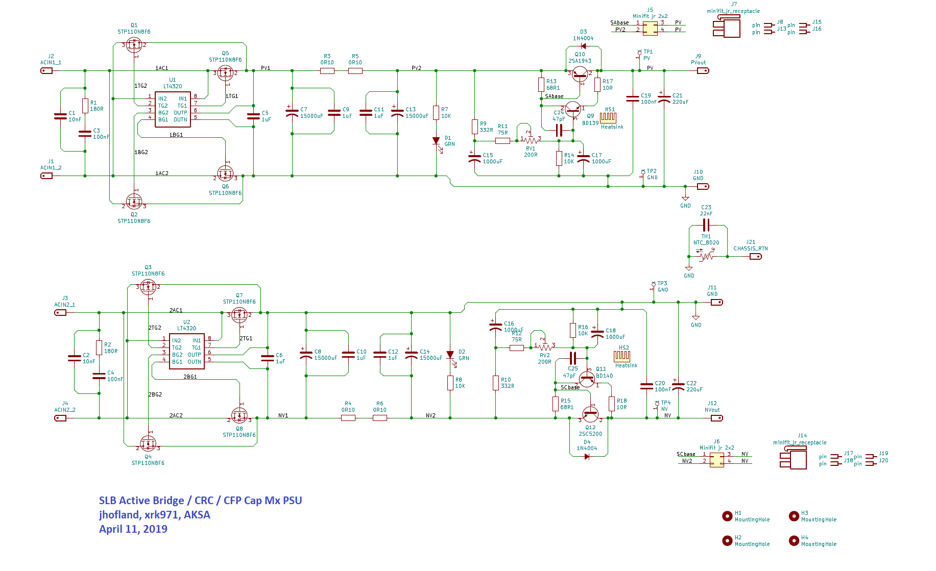
Q10 = 2SA1943N(S1,E,S) --> Cannot find this one with the part ending (S1,E,S). I do have a regular 2SA1943 (not ending with N)
Q12 = 2SC5200N(S1,E,S) --> This one is in stock
Is there a good/better alternative? if yes, any other parts to change? MJL?
Lastly, the NTC 8D20, is this 8 ohms 2A is as the below (cannot find the part number in the BoM)
Mouser : 954-8D2-07LD
Thanks
Do
Just looking at the BoM to place my order and there's a couple parts I cannot find
Q10 = 2SA1943N(S1,E,S) --> Cannot find this one with the part ending (S1,E,S). I do have a regular 2SA1943 (not ending with N)
Q12 = 2SC5200N(S1,E,S) --> This one is in stock
Is there a good/better alternative? if yes, any other parts to change? MJL?
Lastly, the NTC 8D20, is this 8 ohms 2A is as the below (cannot find the part number in the BoM)
Mouser : 954-8D2-07LD
Thanks
Do
Hey Do!
You can use the 2SA1943 in your stash or this one:
https://www.mouser.com/ProductDetail/Toshiba/2SA1943-OQ?qs=EEns8I54Y6Dc4KdnKPmS/Q==
Use a CL60 instead of the 8D20, I actually like it better because it’s a smaller diameter and it is in a tight spot next to faston tabs. It’ll give your fingers a little more wiggle room 😀
https://www.mouser.com/ProductDetail/Amphenol-Advanced-Sensors/CL-60?qs=w3gjcs3NwciEQjXGFRAAAA==
Good luck with your SLB!
Cheers
One SLB assembled and tested under a 4A load (tried 1A first). At 4A per rail, the 0R10 5 watts CRC resistors are getting super hot, but in real life it should be more like a 3A/rail load, since the Alpha Nirvana will be used as load. I'm assembling the 4 ohms version of this amplifier.
One question... I'm currently testing an Antek AN-5222, 22Vac transformer. With a 4A per rail load, I'm getting +/-25Vdc which is just about right, but wondering about the adjustability of output voltage using RV1 and RV2. I've used the supplied BoM @ post #135 and RV1,2 are 200R trimmers. I can only seem to adjust +/-1Vdc, is that supposed to be like that?
Thanks
Do
One SLB assembled and tested under a 4A load (tried 1A first). At 4A per rail, the 0R10 5 watts CRC resistors are getting super hot, but in real life it should be more like a 3A/rail load, since the Alpha Nirvana will be used as load. I'm assembling the 4 ohms version of this amplifier.
Thanks
Do
4a - you're game! 😀 (I made up a load resistor which would draw 3a.)
But I can assure you, when loaded with an AN 4R circuit, those resistors still get super hot. 🙁
Andy
Great news Do! Your cooking away without any smoke 😀
The KOA resistors do get hot, but well within their specs.
The trimpot on the SLB is not to adjust output voltage like a trimpot for a regulated supply would be. It adjusts for voltage drop across the pass transistors. More drop = more ripple reduction = more heat. Adjust so the negative rail is equal to the positive rail. There is less than a 1v range. Sounds like you have a healthy working SLB.
Tip: if you are using flying leads for offboard BJT’s, do not forget to plug them in if you power up under load. You will toast a resistor 😉
Your SLB sounds like it’s working perfectly. The KOA BPRs run about 115C but that’s normal. They are basically ceramic shelled bulk metal resistive heater elements. Just don’t touch them with a bare finger.
Vunce is correct about the pot. It adjusts the output ripple. I typically set it so that there is about 3v drop across the BJT power transistor. The output voltage only varies by about a volt as you have observed.
If you have an Oscope you can monitor the output ripple as you adjust it. It will be a trade off between dropout voltage and ripple. Sometimes I think we should just set it at max drop and put a fixed value there.
Good luck with the rest of your amp.
Thanks guys!
I’m working on the second SLB, almost done!
Not using flying leads, I’ll be connecting power BJTs directly to the PCB.
Thanks!
Do
I’m working on the second SLB, almost done!
Not using flying leads, I’ll be connecting power BJTs directly to the PCB.
Thanks!
Do
So, the delta for Q11, Q12 emitter/collector in reference to ground should be at max ~3v if trimmer is all the way?
Under no load, I get a max of 2v drop. I'll try with the 4A load.
Do
Under no load, I get a max of 2v drop. I'll try with the 4A load.
Do
Last edited:
Checking ripple with scope, I seem to be getting 93+ mV ripple on emitter and 10-12mV on collector, under 4.2A load... Don't know if this is correct or not? Seems a bit higher than the specified results in the thread.
Anything I should check?
Do
Anything I should check?
Do
Checking ripple with scope, I seem to be getting 93+ mV ripple on emitter and 10-12mV on collector, under 4.2A load... Don't know if this is correct or not? Seems a bit higher than the specified results in the thread.
Anything I should check?
Do
Surely, the collector ripple is all that we care about ... and 10-12mV is fine? Particularly when you're drawing 4.2a (rather than 3a)?
Andy
Hi Do,
I vaguely remember that lowering the value of R17 and R18 will decrease ripple but at the expense of possible oscillation. But since you have a scope, you can check. Nominal value is 10R, try dropping to 3.3R. I think that should take the 16mV to about 5mV.
But if you see oscillation, increase a bit to 3.9R or 4.7R.
Hi Do,
I vaguely remember that lowering the value of R17 and R18 will decrease ripple but at the expense of possible oscillation. But since you have a scope, you can check. Nominal value is 10R, try dropping to 3.3R. I think that should take the 16mV to about 5mV.
But if you see oscillation, increase a bit to 3.9R or 4.7R.
Yes, early on in the SLB thread, 3.3R was suggested. So, as I wanted as low a ripple as I could get ... I installed 3.3R for R17 & R18.
However, during the long process of tracking down why my AN 4R amps were oscillating, Hugh suggested that 10R was the right value to use - so I replaced the 3.3R reses.
I've been inspired by Do's post to measure the ripple that I have currently, on the DC rails of one of my amps. Results are:
L ch +ve: 20mV
L ch -ve: 25mV
R ch +ve: 20mV
R ch -ve: 25mV
This is with each SLB powering an AN 4R board.
Interestingly, the -ve ripple wave is much smoother ... the ripple on the +ve rail is kindof like a triangular wave with a big spike!
Can anyone suggest why the ripple on the -ve rail should be smoother than that on the +ve rail? (Note: the fans are driven from the +ve rails.)
Andy
I'll be experimenting a little here, but probably going to test 3R9 and 4R7 just to stay on the safe side.
Thanks
Do
Thanks
Do
If you drive a PWM fan with your supplies, try adding a CLC filter in between to block the noise from the fan drive coming back to your SLB.
If you have something on your bench circa 22uH to 1000uH is fine and add circa 50ohm in parallel to inductor. Caps ranging from 100uF to 1000uF should work.
Differences in positive and negative rail might also be intrinsic differences in N vs P junction BJTs. They are different in performance due to solid state physics.
I was able to achieve circa 1-3mV rms ripple at about 4A but that was with dummy test load and not an actual amp. This can be seen in Post 1.
Last edited:
If you drive a PWM fan with your supplies, try adding a CLC filter in between to block the noise from the fan drive coming back to your SLB.
Thanks, X.
If you are suggesting that a CLC filter will be a good thing if I am using a PWM controller - what about if I'm simply driving the fan via the (resistive) auxiliary cable - which reduces fan speed?
Andy
- Home
- Group Buys
- The SLB (Smooth Like Butter) Active Rect/CRC/Cap Mx Class A Power Supply GB