Hi Lynn,
I hope you get soon a visitor or you find an occasion to make a trip to someone with also good components to hear your SIT-3X.
I am so sure there must be a difference to the XA25 clone. The SITs simply have their own sound signature.
Besides this, CONGRATULATION to your work to develop this amp!
:--))
Hi Lynn,
I hope you get soon a visitor or you find an occasion to make a trip to someone with also good components to hear your SIT-3X.
I am so sure there must be a difference to the XA25 clone. The SITs simply have their own sound signature.
Besides this, CONGRATULATION to your work to develop this amp!
:--))
I am still doing a lot of listening. I have not yet attempted to explore the changes to the sound as the "Schade feedback" pot is changed. That is the pot in the output stage that attenuates the signal to the PFET gate. The setting I am using is one that makes the 4R and 8R spectra look most similar, but is not necessarily one that would emphasize the signature of the SIT. In order to explore the behavior of that pot adjustment, I want to be able to reliably return to previous settings. I dug around in a spare parts box and found a pair of 100R 10-turn pots with 10-turn dials. Exactly what it was looking for. Amazing luck. That is the project for today.
Hi Lynn,
I hope you get soon a visitor or you find an occasion to make a trip to someone with also good components to hear your SIT-3X.
I am so sure there must be a difference to the XA25 clone. The SITs simply have their own sound signature.
Besides this, CONGRATULATION to your work to develop this amp!
:--))
I wonder if the Schade feedback level I have been listening at is reducing the harmonics enough that the sound signature of the SIT is being suppressed.
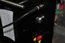
I have installed the 10-turn dial pots for the adjustment of Schade feedback level, making it possible to run reproducible listening tests.
Attachments
I guess you can optimize the shade fb for the impedance of your speakers, for distortion and or the sound you like?
Your going to need a team of listeners while you turn the pot on both channels the same amount.
Then listen again and again to the same music till the wife is MAD, (I mean crazy)!
Wish I was there.
Rush
Your going to need a team of listeners while you turn the pot on both channels the same amount.
Then listen again and again to the same music till the wife is MAD, (I mean crazy)!
Wish I was there.
Rush
I reported earlier about installing multi-turn dial pots for the Schade feedback level. Yesterday, a sound-sensitive neighbor and I had the first experience listening to the SIT3X at a variety of feedback levels. The P6 pot controls the attenuation of the signal from FEOut to the gate of the M1 PFET. The attenuation factor is (approximately) A = .189*X+.811, where X is the dial pot reading in the range 0 to 1.
Conclusion: My old ears were not the cause for believing that the SIT3X sounded like the ZD25 with my initial setting for the Schade feedback level. It require exploration of the effects from P6 (the X-pot).
- I started with feedback pot at X=.7 (A=.945) that I had originally been using that was based of bench measurements. Neither of us could hear a significant difference from the ZD25.
- I increased the feedback level to the pot setting of X=.6 (A=.928) and the SIT began to sing!
- At X=.5 (A=.909) the SIT signature increased. It is difficult to describe but instruments seem to come alive.
- At X=.4 (A=.887) the SIT signature increased further.
Conclusion: My old ears were not the cause for believing that the SIT3X sounded like the ZD25 with my initial setting for the Schade feedback level. It require exploration of the effects from P6 (the X-pot).
The attenuation factor A controls the AC power contribution from the FETs. I have identified 3 particular values of A:
- A_J1ccs is the value of A where J1 acts as a constant current source, not modulating the OS output.
- A_H2null is the value of A where the second harmonic is minimized.
- A_M1ccs is the value of A where M1 acts as a constant current source, not modulating the OS output.
- A_J1ccs < A pull/pull SIT signature magnified? 10dB higher distortion. I haven't listened here.
- A_H2null < A < A_J1ccs push/pull positive phase H2
- A_M1ccs < A < A_H2null push/pull negative phase H2
- A < A_M1ccs push/push SIT signature magnified
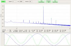
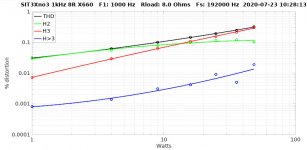
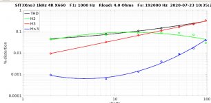
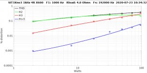
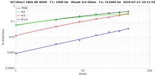
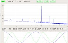
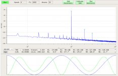
Here are some spectral measurements for the right channel of the SIT3X with the X-pot (Schade feedback level) adjusted such that the PFET M1 acts as a constant current source into an 8R load. This might have some similarities to the FirstWatt SIT1, except that its OS is single-ended common-source rather than common-drain.
- The first two plots show the spectra and residual waveforms for a 1kHz sine wave 1 Watt into 8R and 2 Watts into 4R loads. Note that the spectra and residuals show very little change between the 4R and 8R loads.
- The last two plots show a distortion sweep vs. Watts into 8R and 4R loads. The 2nd harmonic has somewhat "strange" behavior at higher power levels. This might be due to the bias current increasing with higher power levels.
Attachments

This set of plots are with the X-pot at an increased level of Schade feedback, putting the OS stage into the "wonky" push/push mode of operation.
Attachments
Last edited:
More listening yesterday and today. I definitely like the SIT3X adjusted at the single-ended source-follower setting, where the M1 PFET is acting as a current source. This amplifier is a keeper.
Because the folded cascode front-end inverts the phase of the signal, the speaker wires must be connected backwards to obtain positive phase H1 and negative phase H2.
There might be some minor improvements with parameter tuning, but overall I cannot find anything to change in the amplifier.
I measured idle AC power draw at 120V * 3.0A = 360VA, which is 1.5X the idle power of the XA25.
I have not experimented with reducing the idle current from 1.8A to a level where the diyAudio Store Deluxe 5U Aluminum chassis heatsinks would be be keep the temperature rise to 25C, which I estimate to be about 1.5A. If the performance looks good, the existing PCBs should work.
My amplifier power performance measurements are probably very misleading. I have been looking more at the distortion vs. Watts measurements and it is apparent that the opto bias circuits must be dramatically increasing the bias current at high output Wattage.
Tomorrow I will do some bench measurements, looking at the DC current through the M1 PFET drain sense resistor vs. output Watts. When M1 is adjusted as a current source, there is no AC voltage across this resistor and the DC voltage corresponds to the single-ended source-follower bias current.
The real test is to look at the voltage where the output clips for short duration bursts of high amplitude sine waves, such as 10 cycles of 1kHz every 1/2 second. Being short duration, the opto bias circuit current should not change significantly.

indeed! , even if I hate his math oriented approach 🙁
(or I hate - me lacking the same )

Actually, not any math in quite a while. Recently it has been chassis work, PCB assembly, wiring, testing, fixing the parts that smoked 😱, more testing, and recently listening. Finally I am beginning to understand how to make the SITs sing, which wasn't what I had expected. 🙂
Fantastic work Ihquam, I’ve been following this thread from the beginning and it’s been a great read. Thank you for sharing all the details along the way! The SIT threads have been some of the greatest challenges in such a short while. Truly awesome DIY accomplishments.
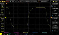
Interesting that the rise and fall behavior are different. Its like the brakes are on for the rise but the fall is a fall off a cliff until you get close to the bottom then the brakes engage. There are amusement park rides that behave that way.
- Home
- Amplifiers
- Pass Labs
- The SIT-3X Amplifier