Just Now! both PSU units are tested and ready to go! CLC filtering om both positive and negative, and classic CL60 inrush limiters.
The rest of the PSU-capacitors will be divided in each of the power amplifiers. 🙂
The Form factor of the PSUs chosen for this build are exactly a vinyl record box set, with rubber feets. 🎺🙂🎸

The rest of the PSU-capacitors will be divided in each of the power amplifiers. 🙂
The Form factor of the PSUs chosen for this build are exactly a vinyl record box set, with rubber feets. 🎺🙂🎸

I was looking for the rectifiers and think I found them (if not you would probably have experienced a loud "bang").
It is a single supply with a DC filter choke in what normally could be Gnd?
Ok.....audio ground will be in the amp chassis at bank of capacitors (at the + as it is a negative supply voltage?).
I was wondering a bit about the safety ground if you transfer this to the amp chassis and also if you have a reference from audio ground to chassis?
My concern was to avoid ground loops........caused by the yellow/green wire to both chassis........with the special DC filter choke arrangement. But I should probably not be concerned 🙂 .......it looks very good! ......and the small toroid is maybe for the "future"......to drive some relays.....as discussed.
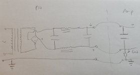
I made a quick hand drawing of what I think the concept is. It is late night so I could have made big mistakes.......but if the concept is like the hand drawing with only one reference from audio gnd to chassis and audio gnd is defined in amp chassis only I am not concerned.
The reference from audio gnd to chassis could be resistor, CL60, galvanic, bridge etc......the resistor symbol is just made to indicate the reference.
The reference from audio gnd to chassis could be resistor, CL60, galvanic, bridge etc......the resistor symbol is just made to indicate the reference.
Attachments
yeah
in short:
PSU case must be connected to safety GND
Amp case must be connected to safety GND
PSU is floating (totally) in PSU case
in amp case, connect (finally) established GND to case through whatever - NTC or NTC//Bridge or NTC//Bridge//cap
there are few other ways to it, while still totally safe, but only this way there are no surprises if by chance PSU case touches AMP case
Last edited:
One thing I maybe would be a bit concerned about is the filter caps placement directly on chassis. Usually the aluminium can itself is "minus" (you can measure)?
The can has plastic insulation but the bottom is not fully insolated. The chassis has "plus" reference so if a can is bugling a bit out "something" could happen. Now aluminium has natural oxidation which will help the electrical insulation but I just wanted to mention it 🙂
Also the amp chassis gets quite hot which could soften the insulation a bit.
An opportunity to learn a PCB design software - a power supply capacitor bank is an easy starter PCB. 🤓
Yea, thats true. And I will surely learn/try PCB creation and design some day, in some future build.
But i really like the solid look and feel of the really old school point to point wireing.
Its just a personal nerdy thing. 🙂🙂🙂
But i really like the solid look and feel of the really old school point to point wireing.
Its just a personal nerdy thing. 🙂🙂🙂
Do you know any clever, reasonably priced solution, to get the resistor network, and the amplifiers ”midpoint” adjustable, by ear, while playing music, by the simple twisting of a knob?

Yea 🙂
So. I will probably have go the classic and slow, but high quality ”manual resistor switching route”.
So. I will probably have go the classic and slow, but high quality ”manual resistor switching route”.
Power supply done mounted in the chassis, both channels done. I just need to finish mounting one channel to its heatsink then it's time to wire up each channel and bias. I'm not quite sure what I was thinking about when I put this massive amplifier and supply in a single 5U chassis.......this thing is heavy and I put the chokes in the back to help the C.G. (center of gravity) 🙄 I ordered some massive rubber pucks to replace the Modushop feet as I think this amp would have shattered them.....

while you're there, to ease settings
Mu pcb, change R1 to 5K6 or 6K8, R3 to 150R
reason, I see you have changed 3W resistances per Ben Mah recipe
Mu pcb, change R1 to 5K6 or 6K8, R3 to 150R
reason, I see you have changed 3W resistances per Ben Mah recipe
Will do, thanks Chokster.while you're there, to ease settings
Mu pcb, change R1 to 5K6 or 6K8, R3 to 150R
reason, I see you have changed 3W resistances per Ben Mah recipe
The more I listen to the Singing Bush, the more it reminds me of the XA-25. It’s more diffuse though, and the sound stage is larger in every direction.
This is an amp that everyone would enjoy, especially if you love tubes the way I do.
This is an amp that everyone would enjoy, especially if you love tubes the way I do.

- Home
- Amplifiers
- Pass Labs
- The Singing Bush