
Fixed a regulated power supply with LT1084
12V DC (filaments in series)
noise always present but attenuated to the point that at the listening distance it does not bother.
With the Lightspeed zero noise but the preamp gain adds vitality .... but it's not a decisive difference
I have to decide by listening calmly.
in any case, the Bush is a fantastic music dispenser. I deliberately did not add plastic capacitors to the output because I want to understand if they are really necessary,
I put a Mundorf M-Lytic AG alone temporarily

since I could not tame the horse ... I mounted a well tamed one.
a few years ago I experimented with the LSK Pre by Juma (another good Serbian guy) inspired by N.Pass and modified by the author himself in the scheme proposed here. I designed the pcb. I thought of using the DCB1 as a buffer in the Lightspeed output, made using the 2SK2145 (also my design).
In addition to the dead silence obtained with the Singing Bush I can say that this preamp sounds really good in its simplicity (apparent) and I don't miss the old tube preamp .... I did poker
Attachments
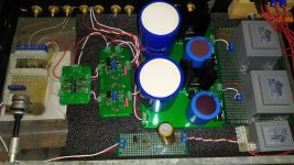
Hello everyone and in particular you Zen Mod. Finally, I managed to mount the singhing bush number two ... this time with the Yamaha 2sk77. the mosfets, are the IXFN140N30P.
I set fire to the powders this afternoon, on the first channel, everything ok up to 20 mv for the buffer and P2 control ... when I connected the drain of the sit, I read on the voltmeter across r5 705mv, while on the drain of the sit 11.8V, if I'm not mistaken. I tried to play with p1 on the Mu card and I went down to 655mv while with P2 on the SIT card, I could only go down from 11.8v. The mosfet heated up a lot. Luckily, I didn't see smoke ... What's going on in your opinion? what should I do? (The photos I took during construction ....)

now, since you have Real McKay, meaning - real 2SK77, and I don't have that one ...... I can only presume that original Papa's data for Iq (which he got for 2SK77B) is most likely the best
so, let me know how you arranged resistors in Mu Section
I believe it could be best to have 5+5 1R resistors, so resulting in 0R2 + 0R2 in Mu section
confirm what you have , then we will proceed
so, let me know how you arranged resistors in Mu Section
I believe it could be best to have 5+5 1R resistors, so resulting in 0R2 + 0R2 in Mu section
confirm what you have , then we will proceed
OK ......
say that you want Papa-prescribed Iq value of 3A2, that's 3A2*0R2 = 640mV across any of 02R rersistor groups in Mu follower
now, we want around rail/2 voltage at output node , plus or minus volt or two; you can play later setting it two volts up or two volts down from Rail/2 and leaving what you like more , sound wise
but for start - lety's say that we are shooting at Rail/2
fact that you have lesser voltage across SIT, meaning you can't reach Rail/2 at output node, means that SIT is not closed enough, resulting in not enough ohms between D and S
we need to choke it/close it more and single logical way is to get more negative voltage to SIT Gate
looking at second schm in post #2 here https://www.diyaudio.com/community/threads/the-singing-bush-tips-n-tricks.357497/post-6279704
desolder R10 (10K) and solder it across R12 (9K1)
or simply replace R12 with 4K7 if you have it in drawer
inform what you got
Hello everyone and in particular you Zen Mod. Finally, I managed to mount the singhing bush number two ... this time with the Yamaha 2sk77. the mosfets, are the IXFN140N30P.
I set fire to the powders this afternoon, on the first channel, everything ok up to 20 mv for the buffer and P2 control ... when I connected the drain of the sit, I read on the voltmeter across r5 705mv, while on the drain of the sit 11.8V, if I'm not mistaken. I tried to play with p1 on the Mu card and I went down to 655mv while with P2 on the SIT card, I could only go down from 11.8v. The mosfet heated up a lot. Luckily, I didn't see smoke ... What's going on in your opinion? what should I do? (The photos I took during construction ....)
say that you want Papa-prescribed Iq value of 3A2, that's 3A2*0R2 = 640mV across any of 02R rersistor groups in Mu follower
now, we want around rail/2 voltage at output node , plus or minus volt or two; you can play later setting it two volts up or two volts down from Rail/2 and leaving what you like more , sound wise
but for start - lety's say that we are shooting at Rail/2
fact that you have lesser voltage across SIT, meaning you can't reach Rail/2 at output node, means that SIT is not closed enough, resulting in not enough ohms between D and S
we need to choke it/close it more and single logical way is to get more negative voltage to SIT Gate
looking at second schm in post #2 here https://www.diyaudio.com/community/threads/the-singing-bush-tips-n-tricks.357497/post-6279704
desolder R10 (10K) and solder it across R12 (9K1)
or simply replace R12 with 4K7 if you have it in drawer
inform what you got
Last edited:
Hi, now I will replace R12 with 4K7. What do you think of the mosfet that heats up so much?OK ......
say that you want Papa-prescribed Iq value of 3A2, that's 3A2*0R2 = 640mV across any of 02R rersistor groups in Mu follower
now, we want around rail/2 voltage at output node , plus or minus volt or two; you can play later setting it two volts up or two volts down from Rail/2 and leaving what you like more , sound wise
but for start - lety's say that we are shooting at Rail/2
fact that you have lesser voltage across SIT, meaning you can't reach Rail/2 at output node, means that SIT is not closed enough, resulting in not enough ohms between D and S
we need to choke it/close it more and single logical way is to get more negative voltage to SIT Gate
looking at second schm in post #2 here https://www.diyaudio.com/community/threads/the-singing-bush-tips-n-tricks.357497/post-6279704
desolder R10 (10K) and solder it across R12 (9K1)
or simply replace R12 with 4K7 if you have it in drawer
inform what you got
reason is simple - mosfet is having too much voltage across it and calc sez that W ( heat) = V * A
in this moment , mosfet is having greater V across than SIT
when you get output node to Rail/2 they will be equal in heat
in this moment , mosfet is having greater V across than SIT
when you get output node to Rail/2 they will be equal in heat
Hi, Now I have 62.7 volts of power rail, 21.43v on the sit drain Max, and 644mv minimum across r5. I want to tell you that when I first turned on the Bush, all the trimmers were at maximum and apart from p1 of the SIT pcb, they remained at maximum. I can only decrease the voltage on the drain or increase the mv of bias.
OK
now replace R11 (1K5) on SIT pcb with 4K7 to 5K6, whatever you have in drawer, then fiddle with P2
if you want lower Iq , even if you are spot on to Papa's (644mV across 0R2 means 3A22), increase value of R1 on Mu pcb (from 8K2 to say 15K) and you can even halve value of R3, from 100R to 51R
start with whatever is easier, on Mu pcb - R3 or R1
all ref to schm in post #2

Thanks Zen Mod, I will continue with the changes tomorrow, undoubtedly, we are on the right track. I can't wait to hear the Yamaha sit singing .... Now, I'm too tired and working tomorrow morning. Good night.
Hi Zen Mod... even if I didn't dream of the Alfa Rossa, I did my homework... on the first channel, after some tests, it works correctly by mounting r11 5k6 and r12 4k7 on the SIT pcb. No changes to the Mu.
The SIT now heats up damnably, I really think that the fans cannot be an optional. I go to work on the second channel and then I try to set everything up. You are great! See you later, I'll let you know if even with the second channel, we're ok.
The SIT now heats up damnably, I really think that the fans cannot be an optional. I go to work on the second channel and then I try to set everything up. You are great! See you later, I'll let you know if even with the second channel, we're ok.
give us few more pics of SIT thermal arrangement
if you don't have proper transfer/enough area between SIT hsink and main hsinks, you have a problem
if you don't have proper transfer/enough area between SIT hsink and main hsinks, you have a problem
The original Yamaha heatsink is fixed to the heatsink of the case with two long screws and makes perfect contact, I also put the thermal paste. Instead, with the second channel, I can't go above 25v with 635mv of bias ... I mounted the same resistors as the first channel. What I do?
- Home
- Amplifiers
- Pass Labs
- The Singing Bush Tips 'n' Tricks