TO-120 also like BD ?
Do you mean TO-126 BD type power trannies ?
Yes typo, like BD139 etc
The oscilations appear only if I shorten sim time to 400u and max step 100n.
Anyway with this version (cross between mean v12 and v12r) I can use lower value output cap....
Anyway with this version (cross between mean v12 and v12r) I can use lower value output cap....
Ah, a pole zero across the Ccb of the controlling BJT.C2 and R10
Do you realise that your implementation does not require the use of k170 jFETs.
Many more easily available and cheaper jFETs will work in the two locations.
Yes Andrew
I normally use k117 for ccs but do not have LTSpice models for those.
K117 catch up faster.
PS: Would you please visit the thread http://www.diyaudio.com/forums/soli...r-amplifier-assemblage-vii-2.html#post4862286
I would really apreciate your input regarding the TX I need for this power amp.
Best
Ricardo
any reason why DCSTB power supply for headamp wouldn't work well as a regulator for digital 3.3v output (maybe with mosfet as pass transistor)?
I'm just just curious how it would fare...
I'm just just curious how it would fare...

any reason why DCSTB power supply for headamp wouldn't work well as a regulator for digital 3.3v output (maybe with mosfet as pass transistor)?
I'm just just curious how it would fare...
It would work well as far as a glorified Cmult goes. But with Mosfet it would do worse than originally designed. More heat and possibly lower spec too.
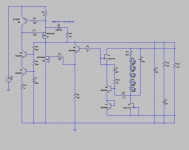
Could not resist to serialize reflektor:
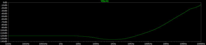
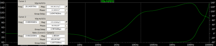
PSRR and output impedance graphs are attached.
Why you would want output impedance in the Ohms range when it was in the sub mOhm range? Or its simply something wrong with the Y axis scaling.
The graph goes up to 100MHz (1Ohm at ~10MHz). In the audio band the impedance is below 300uOhm, see the attached 1mHz-200KHz plot.Why you would want output impedance in the Ohms range when it was in the sub mOhm range? Or its simply something wrong with the Y axis scaling.
Attachments

Although Toshiba has discontinued all of the leaded parts afaik, a dual in SM exists, the 2SK2145, which might be useable with some sort of adapter socket. They also tied the two channels together instead of bringing both ends of them out and using a sixth pin, which I found remarkably short-sighted.
edit: the 2145 is essentially two SK117
Thanks for finding this. Has anyone tried these with adapter or leads soldered (I assume using half of this chip)?
Thanks for finding this. Has anyone tried these with adapter or leads soldered (I assume using half of this chip)?
Never mind, as noted in manual 2SK880GR is suitable.
Last edited:
Bias currents
For the original simplistic design, post #8, what is the bias current set by J1 and J2? I don't have any 2SK170's on hand to measure.
I'm considering this for my next project, but 170's cost (almost) as much as gold, and I would rather use 2SK117, 2N5457, BF256, or other. For a constant current source, any small signal JFET with a gate-source resistor should in theory work, maybe not as well as the 170's but good enough for this project. I would like to set the bias currents the same as in the original design.
The version shown in post7584 does not require any sk170.
The sk170 (or any very low pinch off voltage jFET of similar current rating) is only required where the operational Vds is very low.
Medium Vpinchoff, medium gm devices would do.
- Status
- Not open for further replies.
- Home
- Amplifiers
- Power Supplies
- The simplistic Salas low voltage shunt regulator