Medium Vpinchoff, medium gm devices would do.
Do you mean medium pinchoff/gm devices would work in post #7584 schematic, and not in post #8 schematic?
The JFET has only one VBE-drop (~0.6V) to work with. Most jellybean JFETs I have tried needed at least double that. If you have a negative rail handy, you can tie the JFET to that and use whatever part you have lying around. I've done this successfully with the symmetrical dual salas, which you can find in post 7192 of this thread.
I reckon it comes back to using Borbely's advice:
ensure the working Vds across a jFET is at least double it's Vpinchoff.
A low Idss, high gm device can have a Vpinch off around 0.3Vgs
It is this that allows an sk170 to operate with a Vds of ~0.6V
Swap in a medium gm device and it won't work as well as the high gm device simply because Vds is too small relative to Vpinch off.
BTW,
a BL graded sk170 has a higher V pinch off than a GR graded. It is better to use GR where the Vds is low and the current requirement is also low.
post8 J1 and post1 Q5, must be a low pinch off, high gm device.
Ahhh... I understand. I have always had a soft spot for low part-count designs, so I wanted to try the original very simplistic design. If I tackled the project, I would build 2 positive supplies, because with OSH Park you get 3 boards per order, so 2 for the project and 1 for spare. Small parts count = small boards = smaller chassis size and therefore my interest. Thanks for your help.
I suggested early on that building two negative versions might give a better result.
I have no evidence to support that.
It's based on the specifications of Nch compared to Pch mosFETs.
I have no evidence to support that.
It's based on the specifications of Nch compared to Pch mosFETs.
Salas: If feeding a circuit which needs large input caps for stability.. is the only way to get the SSLV1.1 to not osciallate by adding series resistor (small) or tying the sense wiring to Vout at the reg instead of at the load? Or is there any other way to prevent oscillation..?
If you mean large local rail capacitors they usually don't lead to instability. Especially if there is some ESR in them. Keeping it two wire it may also help as you mentioned.
I was thinking about changing Buffalo III-SE local regulators to series regs - and they all have input caps around 100uF (elyt-caps).. you don't think this is going to be an trouble?
It might be...
As you note, the new TPA series regs have a fair amount of C onboard. I found that powering the Legato 3 with BiB regs worked way better by changing the 6 100 uF electrolytic caps to .1 uF film caps. With the 600 uF onboard the BiB regs oscillated. If you have 5 of the new TPA series regs, you will have quite a bit of capacitance onboard, and should at least check the BiB with a 'scope for oscillations.
I find I prefer the Reflektor to power the B-IIIse board anyway, and I have not had oscillation using the Reflektor to power other digital boards with around 500-600 uF local decoupling.
I was thinking about changing Buffalo III-SE local regulators to series regs - and they all have input caps around 100uF (elyt-caps).. you don't think this is going to be an trouble?
As you note, the new TPA series regs have a fair amount of C onboard. I found that powering the Legato 3 with BiB regs worked way better by changing the 6 100 uF electrolytic caps to .1 uF film caps. With the 600 uF onboard the BiB regs oscillated. If you have 5 of the new TPA series regs, you will have quite a bit of capacitance onboard, and should at least check the BiB with a 'scope for oscillations.
I find I prefer the Reflektor to power the B-IIIse board anyway, and I have not had oscillation using the Reflektor to power other digital boards with around 500-600 uF local decoupling.
hi Salas, I've to supply a Cubie Truck (streaming device) and a tera hard disk with 5V. I checked the current sinked by both the devices when they play music, about 0.8A in avarege with peaks of 1.1A.
What schematic I've to use? I think one with IRFP9240.
I remember a post with schematic for supply 2A ( a little power amp), but I don't know
where in this big thread. Can you help me?
Happy new years to everyone!
What schematic I've to use? I think one with IRFP9240.
I remember a post with schematic for supply 2A ( a little power amp), but I don't know
where in this big thread. Can you help me?
Happy new years to everyone!
SSLV1.1 but with IRF9640 CCS Mosfet instead of 9610 should cover your needs
You maybe mean that post? http://www.diyaudio.com/forums/powe...tize-general-shunt-reg-pcb-2.html#post1995942
Happy new year to you too 🙂
You maybe mean that post? http://www.diyaudio.com/forums/powe...tize-general-shunt-reg-pcb-2.html#post1995942
Happy new year to you too 🙂
I do not remember if I posted this before, but a conversation with a friend last night reminded me it is worth sharing here.
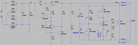
Some time ago while I was experimenting with BiB I smoked plenty of 2SK170 when I shorted the output. Depending on the type (combination of ESR and capacitance) of capacitor filtering the reference voltage C4, the pn-junction of Q5 (according to my schematic below) conducts too much current for a small period of time. The solution was to use protection smd Schottky diode D2. I tested both SS14 and MBR0504 and they worked fine, saving Q5 when shorting the output.
Some time ago while I was experimenting with BiB I smoked plenty of 2SK170 when I shorted the output. Depending on the type (combination of ESR and capacitance) of capacitor filtering the reference voltage C4, the pn-junction of Q5 (according to my schematic below) conducts too much current for a small period of time. The solution was to use protection smd Schottky diode D2. I tested both SS14 and MBR0504 and they worked fine, saving Q5 when shorting the output.
Attachments
Yes it can happen in a short if with large Vref filtering capacitor (>220uF usually) and its good you posted this reminder/solution for those using big capacitors when there is a chance they short the wires outputs.
It is quite an easy mod when using smd diodes and it saves you a lot of trouble later... and a handful of trashed 2SK117's 😎
Why so many? You were carrying out systematic shoring tests? Vout level plays a significant role in that also as well as ESR.
Why so many? You were carrying out systematic shoring tests?
Yes 😱 Then I ran some similations in LTSpice to confirm my mishaps.
The funny thing was that I had no problems with my RIAA regulator with 220uF Silmic II (Vref lytic) and Vout=28V. But my DAC regulator with Vout=5V and Nichicon KA 1000uF caused me all these troubles 😀
So, it is indeed a combination of Cvref value, ESR and Vout, i.e. energy transfered through the Q5 pn junction during transients produced by shorting the output 😉
- Status
- Not open for further replies.
- Home
- Amplifiers
- Power Supplies
- The simplistic Salas low voltage shunt regulator