I give it up. I cant follow and cant control what's happening there.
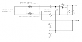
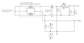
But I told to "Disconnect central conductor at DUT, and short it inside preamp!"
I've attached two runs with the DUT connected like before (signal and shield connected)
But I told to "Disconnect central conductor at DUT, and short it inside preamp!"
While the input cable was... ? And DUT was... ?
I wrote "and the BNC connector left open", so there was no input cable and hence no DUT connected. You didn't ask me to to this, but I thought this would be sort of a reference - input is shorted in both cases, but in one case the input cable is connected and in the other case it is not.
What about central connector in the preamp?
In the preamp it was still connected to the small 2-pin molex connector, in which I put a wire link to short the input.
But I'm too tired to investigate what you did.
I'm trying my best to show you the measurement results you're asking for. Might still be true that I don't grasp what you want me to do at first time, so I'm giving a short description of what I did.
You test a complete system. 1 strong disturbance source can hide many other saller ones. If lab supply is earthed on it's output GND, then this is a strong ground loop.
The lab psu is only earthed on its case, which has no galvanic contact to the output connectors or secondary ground, so there should be no ground loop in this case.
Don't bother make a case for preamp (yet). There are no sensitive parts, except input cable, but you can't eliminate this with a case.
The preamp has a case already, but the DUT has none. It was the DUT that I put in the biscuit tin, not the preamp. And it does indeed make a difference in the spectrum wether the preamp's lid is removed or not.
But I told to "Disconnect central conductor at DUT, and short it inside preamp!"
And that's exactly what I did and what is shown in the first picture attached to that post. The other two pictures show the spectrum with the DUT connected like before and come together with the ASCII files for the waveform, because earlier you wrote: "All of them can be interesting, but the one with DUT may show something special.". That's why I re-did the measurements with the DUT to save the ASCII waveform data with! The measurement with the cable only was of such a low value overall, that you can basically see nothing more than some noise in the waveform, while the waveform of the other measurements show a distinct 50Hz wave.
Not sure if anybody is still listening, but this is is what I just tried out of curiosity, lacking a decent balanced interconnect at the moment. Overall noise performance got worse by almost 20dB and I have no idea what might be the cause, except for the resistance of two feet of RCA interconnect cable. 😕
Attachments

Adding the proposed 10R ground breaker helps with the noise floor, but all the other disturbances are back again.
At 50 Hz I see -90 dB, while the previous picture shows -70 dB.
😕
I would like to help, but I cant.
At 50 Hz I see -90 dB, while the previous picture shows -70 dB.
😕
I would like to help, but I cant.
The first picture shows -70dB at 100Hz, not at 50Hz. Look again.
The first picture shows -70dB at 100Hz, not at 50Hz. Look again.
Oops! You are right! But then there must be something very important that is not on the schematic! (Or maybe ringing...)
Yes, probably its ringing. Instead of R4, try a capacitor!
Last edited:
How much capacitance? pF, nF, uF?
Yes, but not here at home. Have one at work, can use it tomorrow. What should I look for and where?
Do you have scope?
Yes, but not here at home. Have one at work, can use it tomorrow. What should I look for and where?
Try some values from 10 nF to 10 uF!
On the output there must be some periodical high freq signal with quite high amplitude.
On the output there must be some periodical high freq signal with quite high amplitude.
There was some ringing going on. I could not see any on the output with my 20MHz scope at 5mV/Div., but on the supply lines of the LT1028 was something to be seen. It was roughly on the order of 5mVpp at around 25MHz and I could not get rid of it by adding or removing bypass capacitors at the opamp. The only thing that made the ringing disappear completely was either to a) reduce the power supply to +- 5V or lower or b) remove the capacitors over the feedback resistors! I had removed the one for the 60dB setting first and was thus able to switch the ringing on and off with the 40/60dB switch.
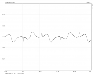
So now I have removed those caps the ringing is gone, but the collected noise of the input cable is still there. Most of that noise in the kHz range seems to come out of my computer, since it increases a little when I put the shorted input cable closer to the pc. On the other hand 50Hz is excessive when I put the cable above my lab psu (see waveform).
It seems to me the only thing I can do to reduce the noise pickup further is to increase the distance between [DUT and preamp] to the pc and the psu (or use battery power). What interests me the most at the moment is to know how an instrumentation amp would perform under this circumstances.
I have yet to try to replace R4 with a capacitor, albeit the difference between R4 in circuit or out of circuit is almost non-existent anymore, now that the ringing is gone.
Attachments
This is about as good as it gets when putting the preamp with shorted input cable (no DUT connected) as far away from pc and psu as cable length permits. Black trace with lab psu and red trace with battery power. I could almost live with that, but I suspect the noise to increase considerably again as soon as the (mains powered) DUT is connected and powered up.
Attachments
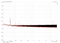
upto 450Hz it is mains fundamental and it's harmonics.
The mains 50Hz could be entering via a different route from the 100Hz and up harmonics.
There could be two routes to find and to try to improve.
The mains 50Hz could be entering via a different route from the 100Hz and up harmonics.
There could be two routes to find and to try to improve.
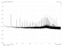
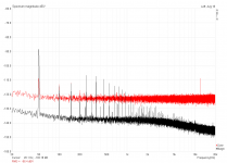
This is what I get when I connect the DUT and fire it up. 50Hz is increased by 20dB (kinda like I suggested), but the noise floor is decreased by 15dB and more! Can the output impedance of the dut be that much lower than the shorted measurement cable alone?
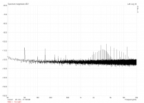
Edit: There must have something went wrong. The second image shows the running DUT with 40dB and 60dB preamp gain (on the same scale). This looks much more realistic.
Edit: There must have something went wrong. The second image shows the running DUT with 40dB and 60dB preamp gain (on the same scale). This looks much more realistic.
Attachments

Last edited:
Its between 0.5-1 mOhm right at the M2 output nodes if your DUT is your IRFP9240/240 SSLV build when running 200mA spare or more
It is.
The second image shows ~-115dB @ 1kHz (instead of almost -140dB) while the shorted cable is more like -124dB. Maybe the preamp got stuck to a rail somehow and thus produced such a strange result.
The second image shows ~-115dB @ 1kHz (instead of almost -140dB) while the shorted cable is more like -124dB. Maybe the preamp got stuck to a rail somehow and thus produced such a strange result.
Maybe a higher impedance lower value coupling capacitor than before in between DUT and probe cable changes results somehow?
There's a coupling cap inside the preamp (which hasn't been changed) and none between DUT and measurement cable.
- Status
- Not open for further replies.
- Home
- Amplifiers
- Power Supplies
- The simplistic Salas low voltage shunt regulator