This is what I get when I connect the DUT and fire it up. 50Hz is increased by 20dB (kinda like I suggested), but the noise floor is decreased by 15dB and more! Can the output impedance of the dut be that much lower than the shorted measurement cable alone?
Edit: There must have something went wrong. The second image shows the running DUT with 40dB and 60dB preamp gain (on the same scale). This looks much more realistic.
Yes, this seems more realistic and tells that at 50 Hz there is enough current to drop significant voltage on output cable.
Unfortunately I can't identify the source of the rest. And noise decreasing is totally misterious.
Can the output impedance of the dut be that much lower than the shorted measurement cable alone?
You know it can't.
Still there must be some easter egg. I don't know what and where. If I were there I could look at the whole thing and could measure, try some things, but this way (on-line) it takes ages.
Based on the current pictures the problem arises on the input. I'm not convinced the ringing is really gone. Maybe it shifted to higher freq. I tell this because of the noise floor anomaly. It shouldn't depend on input impedance this much unless there is ringing.
By the way, I don't know about setting of FFT, but as an aproximation you have 1 uV of white noise on input. This is roughly 10 times more then expected.
Well, noise figure can also be increased due to ESD or overheating of the semiconductor. I see your soldering skill is good enough, but I can't see ESD (and overload) protection on input. Maybe OPA is damaged. First you should measure DC voltages, then try replacing OPA!
I don't know why I didn't realise this earlyer. You definitely overdrive OPA regularly at every connecting to DUT or when you switch it on.
What is this?
http://www.diyaudio.com/forums/atta...las-low-voltage-shunt-regulator-psu-noise.png
Last edited:
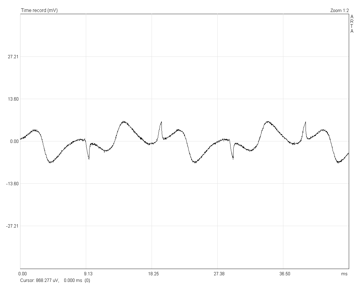
This is the waveform I get when I put the shorted measurement cable really close to the lab psu that powers the preamp.
What should I do against overdriving the opamp? Add some diodes from input to ground?
And what else can I try against ringing? There's not much left except for a completely new layout.
What should I do against overdriving the opamp? Add some diodes from input to ground?
And what else can I try against ringing? There's not much left except for a completely new layout.
"First you should measure DC voltages, then try replacing OPA!"
Overdrive protection: 2+2 antiparallel diode on both + and - inputs.
Maybe you could try to do something with it.
Overdrive protection: 2+2 antiparallel diode on both + and - inputs.
the lab psu that powers the preamp
Maybe you could try to do something with it.
Here're the DC voltages:
Added protection diodes to the inputs.
Added an overcompensation cap of 220pF between pins 5 and 6. This reduces noise visibly on the scope. I will have a look at the spectrum this evening. I have to order another opamp prior to replacing it.
Code:
Pin	Voltage
---------------
1	 14.528
2	- 0.0023
3	- 0.0023
4	-14.660
5	-13.193
6	- 2.3xxx, slowly dropping
7	 14.667
8	 14.532
Added protection diodes to the inputs.
Added an overcompensation cap of 220pF between pins 5 and 6. This reduces noise visibly on the scope. I will have a look at the spectrum this evening. I have to order another opamp prior to replacing it.
Now with 14.999V supply voltage, the DC at the output is in the range of 1.3V and slowly climbing (like 0.1V in a minute or so, didn't watch it for longer than a couple of seconds).
Forgot to mention that that DC scales with gain, ie. it is now only 0.13V when I switch down to 40dB.
Forgot to mention that that DC scales with gain, ie. it is now only 0.13V when I switch down to 40dB.
Here're the DC voltages:
Code:Pin Voltage --------------- 1 14.528 2 - 0.0023 3 - 0.0023 4 -14.660 5 -13.193 6 - 2.3xxx, slowly dropping 7 14.667 8 14.532
I hope there was no DC voltage connected to input.
Input bias current is 2.3mV/4.7k=500nA, and it ought to be lower then 180 nA. It seems to be damaged.
I hope there was no DC voltage connected to input.
No, input cable was shorted.
Input bias current is 2.3mV/4.7k=500nA, and it ought to be lower then 180 nA. It seems to be damaged.
Just noticed that I had changed that 4k7 to 47k while I was trying to find the source of the ringing. Sorry for not telling that in the first place, but it escaped me until just now when I put the thing back together 😱.
Measured overall current consumption also, which is 14mA for each positive and negative supply. LT1028 datasheets quotes something in the range of 10mA, so together with a NE5534 this looks about right to me.
Spectrum doesn't look any different. Noise bandwidth is probably less now due to the compensation cap, but that surely doesn't show on the soundcard up to 20kHz. The datasheet shows a nasty noise spike around 300kHz, which is probably dampened down now and thus the scope plot looks cleaner than before.
Guess I'll have to shell out another 10 bucks then to get a new opamp. If the new one isn't any better than the current one, I can use them both to build an instrumentation amp next...
Guess I'll have to shell out another 10 bucks then to get a new opamp. If the new one isn't any better than the current one, I can use them both to build an instrumentation amp next...
Salas, around post #7000 you advised me to use IRF9610 for the current source and IRF9530 for the shunt. Do you have any suggestions for N-channel devices in TO-220 also? Or should I simply pick anything with a high current capability and fairly low RDSon?
IRF610 and IRF530. Those will make the other polarity close in general characteristics. The capacitive specs are more important.
Turning it around as series topologically looks ok in your schematic but I would worry about stability issues in practice. Better breadboard it to test it does not oscillate.
so far so good...nothing weird on the multimeter

no bypass capacitor nor pot (yes, that is a pot above the LED!) in there (contrary to what schematic shows, and no gate resistor)
next... solder to pcb(with pot, bypass cap,gate resistors)!
anything special i should be careful of before connecting to dac, if nothing weird is detected on multimeter?
Attachments

Last edited:
Your schematic is not understandable, and your description makes it even more fuzzy. What do you mean gate resistor?
No short circuit protection. This can be a problem.
A scope is needed to check HF stability, however the basic topology is quite stable.
No short circuit protection. This can be a problem.
A scope is needed to check HF stability, however the basic topology is quite stable.
so far so good...nothing weird on the multimeter
no bypass capacitor nor pot (yes, that is a pot above the LED!) in there (contrary to what schematic shows, and no gate resistor)
next... solder to pcb(with pot, bypass cap,gate resistors)!
anything special i should be careful of before connecting to dac, if nothing weird is detected on multimeter?
The DMM does not have the bandwidth or the sensitivity to catch MHZ mV level oscillation if there. When not having the proper test gear an AM portable radio brought near it can sometimes become noisy as an indication. Can still be OK on its own but the real dynamic load may set it off. Sure clue of such an anomaly if not evasive and erratic would be steady hum and buzz or weird sonic that wasn't there before when tested as PSU to an audio circuit. If all will sound well maybe its all really well on the other hand. Especially if the HF transients won't harden up. Don't use too high gatestopper value and fuse it's DC input on first test.
Your schematic is not understandable, and your description makes it even more fuzzy. What do you mean gate resistor?
No short circuit protection. This can be a problem.
A scope is needed to check HF stability, however the basic topology is quite stable.
see a few pages earlier...i posted a schematic. the one on the pic is just to help me see if everything is connected the right way.
for short circuit, i thought of a resistor(10 ohm range) in line . i always use one when my psu has no current limit protection and i'm experimenting, like in this case. And i always fuse the AC line
i have access to a scope...not for now anyway.
I'll jusge to the ear and compare to other stable regs...
The DMM does not have the bandwidth or the sensitivity to catch MHZ mV level oscillation if there. When not having the proper test gear an AM portable radio brought near it can sometimes become noisy as an indication. Can still be OK on its own but the real dynamic load may set it off. Sure clue of such an anomaly if not evasive and erratic would be steady hum and buzz or weird sonic that wasn't there before when tested as PSU to an audio circuit. If all will sound well maybe its all really well on the other hand. Especially if the HF transients won't harden up. Don't use too high gatestopper value and fuse it's DC input on first test.
can HF transients be handled with local decoupling?
if it s not dangerous for my gear, i'll give it a shot, just in case it sounds good.
but if it may go bad at any moment, maybe i'll just build the "diyaudio superreg" instead...
too bad i dont have a scope.
- Status
- Not open for further replies.
- Home
- Amplifiers
- Power Supplies
- The simplistic Salas low voltage shunt regulator