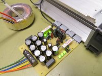
Alright. Congrats.Thanks 😱. It's actually not as bad as I imagined in the first place. By rotating some of the transistors I was able to populate the board in a normal way and didn't have to solder the caps from the top side.
The good thing: It actually works like it's supposed to. When I set the jumper to the standard (ground referenced) setting it doesn't work with BF256B, kinda like the sim suggested. I'll try some SK117 (which should exist in the workshop) and see what a difference it makes.
A photo and some scope plots are soon to follow, but the proper measurement might take me some more time, since I just received my building approval these days.

Thanks guys 🙂.
The SK117 actually works with ground reference, but it takes roughly 15 seconds for the voltage to rise up to its value. Noise-wise I can see no difference on the scope (no wonder...), but to my untrained eyes the noise looks like it's rather on the high side. Actually I expected it to be pretty much invisible on the scope... 😕
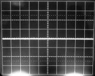
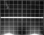
The plots show the grounded scope set to 5mV/Div and in AC mode connected to the positive output. Spectrum plot recorded with the PC will follow once I find the time.
The SK117 actually works with ground reference, but it takes roughly 15 seconds for the voltage to rise up to its value. Noise-wise I can see no difference on the scope (no wonder...), but to my untrained eyes the noise looks like it's rather on the high side. Actually I expected it to be pretty much invisible on the scope... 😕
The plots show the grounded scope set to 5mV/Div and in AC mode connected to the positive output. Spectrum plot recorded with the PC will follow once I find the time.
Attachments
a 2mV sensitivity would only show high noise levels. Maybe you could see 0.2mVpp as a widening of the almost flat trace. More likely you would need 0.5mVpp to see some semblance of a noise waveform. But your scope will probably not be able to lock on to any cycle so you wont see the waveforms and thus not see where in the frequency band the noise is dominant.
For low noise you need far greater sensitivity.
Buy/build a +40dB Low Noise Amplifier (LNA) to investigate medium noise sources.
+60dB or +80dB LNA would be needed for low noise sources.
There are a couple of LNA projects in this Forum.
For low noise you need far greater sensitivity.
Buy/build a +40dB Low Noise Amplifier (LNA) to investigate medium noise sources.
+60dB or +80dB LNA would be needed for low noise sources.
There are a couple of LNA projects in this Forum.
Last edited:
I have already built a LNA and will use it when measuring with the PC. The scope was set to line trigger and as you can see the output noise is clearly visible. I somehow expected it to be so low that it won't (or just barely) be visible with the scope and no additional LNA.
You're ahead of me.I have already built a LNA .....
I have the PCBs and still unpopulated after a couple of years. Some of the ICs are very expensive, but I will bite the bullet and get a move on.
Thanks guys 🙂.
The SK117 actually works with ground reference, but it takes roughly 15 seconds for the voltage to rise up to its value. Noise-wise I can see no difference on the scope (no wonder...), but to my untrained eyes the noise looks like it's rather on the high side. Actually I expected it to be pretty much invisible on the scope... 😕
The plots show the grounded scope set to 5mV/Div and in AC mode connected to the positive output. Spectrum plot recorded with the PC will follow once I find the time.
The 15 secs are to charge up the 1000uF Vref capacitor.
Over many MHZ bandwidth when using oscilloscope some noise must be visible else it would be broken. Integrating noise over tremendous bandwidth is presenting a huge area of noise in brief. Oscilloscope is to mainly check there is no oscillation somewhere and nothing unusual is going on.
*Actually your measuring a PSU with a scope is quite clean. Life can be harder to others. Check out this Dave Jones video for instance: https://www.youtube.com/watch?v=BFLZm4LbzQU
You're ahead of me. (...) Some of the ICs are very expensive (...)
Mine wasn't that expensive... Schematic
The 15 secs are to charge up the 1000uF Vref capacitor.
Yes, but with the cross-referenced BF's it takes only three secs.
Over many MHZ bandwidth when using oscilloscope some noise must be visible else it would be broken. Integrating noise over tremendous bandwidth is presenting a huge area of noise in brief.
Sounds good 🙂. We'll see what else the FFT reveals.
Don't compare panel switch grounded scope, compare PSU turned off remaining connected so to include the test wire open loop to the scope.
Yes, but with the cross-referenced BF's it takes only three secs.
Because many mA higher to charging target than 0.6V biased weaker K117s already. Anyway, if with low noise ref you won't need so big a capacitor anymore. Common type Zeners are pink noise generators of some rightful fame.🙂
Don't compare panel switch grounded scope, compare PSU turned off remaining connected so to include the test wire open loop to the scope.
That's only slightly more noise than with panel switch ground. The measured noise is visibly more than either scope grounded or psu switched off.
more disappointments
🙁 EDIT: second sample is identical
On Semi parts arrived today. The first one tested, at 10mA and just ref tied to the cathode for ~2.5V, is about the so-so average noise spectral density of 127nV/sq rt Hz. I'll test a couple more, but the datasheet typical is probably way too optimistic. Unlike the LED string noise I published on recently in the Blowtorch thread, the noise density is the same whether it's the 22kHz lowpass or the 80kHz.The first SPX431 was actually worse than a JRC 431, about 155nV/sq rt Hz in an 80kHz NBW. The noise was insensitive to operating current between 1mA and 10mA.
The SOT-23-3 SPX2431 was somewhat quieter, but still well above the datasheet typical, at about 96nV/sq rt Hz under similar conditions. I could test more but I would repurpose my test socket rather than trying to solder to them, and I don't want to spend the time right now. Another disadvantage of the 2431 is a max cathode voltage of 20V. They are almost certainly different chips than their 431.
However, while searching unsuccessfully for the JRC spec, I noticed that the On Semi part is supposedly quieter than the run-of-the-mill, at about 48nV/sq rt Hz. And it has the advantage of existing in TO-92.
So I will try to get some of those now.
🙁 EDIT: second sample is identical
Last edited:
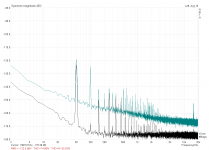
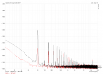
Just a first measurement on the quick. Black shows the noise floor with external 60dB preamp powered on and the positive Salas connected but powered off. Teal shows the psu powered up with BF256B's and no external load. More extensive testing will follow this evening if nothing gets in the way...
Attachments
What does the spectrum look like with the preamp disconnected from the regulator and the input shorted?Just a first measurement on the quick. Black shows the noise floor with external 60dB preamp powered on and the positive Salas connected but powered off. Teal shows the psu powered up with BF256B's and no external load. More extensive testing will follow this evening if nothing gets in the way...
Baseline looks consistent enough with previous measurements of chip regs in his signature link I guess.
An externally hosted image should be here but it was not working when we last tested it.
What does the spectrum look like with the preamp disconnected from the regulator and the input shorted?
Red = 60dB preamp with input shorted (paperclip in BNC jack 😱)
Black = 60dB preamp with Salas connected but powered off
Attachments
Red = 60dB preamp with input shorted (paperclip in BNC jack 😱)
Black = 60dB preamp with Salas connected but powered off
Thanks. So I would experiment with the orientation of the regulator to see if the 50Hz nulls a bit. It looks like something is a substantial pickup loop.
If this is true there is also the possibility that such loops are also picking up substantial energy out-of-band, which may be detected and contribute to the apparent noise level. I know my bench environment is terrible in these days of RF everywhere. I have to use a bandlimited and battery-powered preamp to really see what is going on with low-noise circuits.
- Status
- Not open for further replies.
- Home
- Amplifiers
- Power Supplies
- The simplistic Salas low voltage shunt regulator