8V*1.3A=10.4W it will hold long term if you will make sure that its internal temperature will stay under 100C. With junction to case 3.35C/W characteristic what temperature you measure on that MOSFET's case its 35C more internally for 10.4W. It blows at 175C. Its Ciss at -8V VDS is 360pF (nominal figure is at -25V). IRF9610 has under 200pF at -8V. (-) Because P-MOS. Each time we double the operating temperature of electronics they live four times less is a rule of thumb. Let us know how it went and if any better with AMB Sigma11.
This is hot
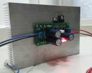
Replaced R1 with 0R47 to give 1.3A, mounted on a big heatsink and tested. At room temperature of 30 degC, it has lasted 1 hour without burning, but it's really hot - I can touch M2 with my fingers for 30 seconds but no more, M1 is less hot but not by far. I guess this will make a pretty good heater in winter.
I just remember Raspberry Pi is using 5V, so I'll need to find a tranformer with 9V secondary before I can test, otherwise Vds is probably too high for M1.
Attachments
the device will run cooler with the sink fins standing vertical.
The device will run slightly cooler when it is just below middle height, rather than just above middle height.
The device will run slightly cooler when it is just below middle height, rather than just above middle height.
Reflektor-D tests
Playing around a Reflektor-D proto these days. Its a configuration idea focused on being handy for powering digital circuits.
To can run 300mA, 400mA, 500mA, 600mA CCS with standard predetermined Rset values using board-level sinks. In combination with proper off-loading by the client circuit's draw of course.
For 3.3V, (3.6V), 5.0V, (7.0V) by combining LEDS mainly. With same parts beyond the CCS and Vref setting ones.
Good stuff I see for now: Steady Vo after very little negative drift from cold to hot only 0.05V, zero overshoot on/off behavior (essential not to kill DAC chips etc.).
Easy to build. No rectification ripple, EMI, or self oscillation appearing on the output over a 200MHZ bandwidth. 20MHZ wide-band noise same as the scope's self limit.
Accepts AC when hosting bridge diodes and a main capacitor filter, or accepts raw DC to a connector and decoupling where the main capacitor would otherwise be.
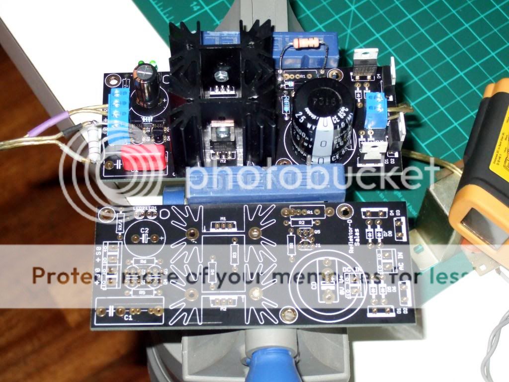
Proto build and spare board
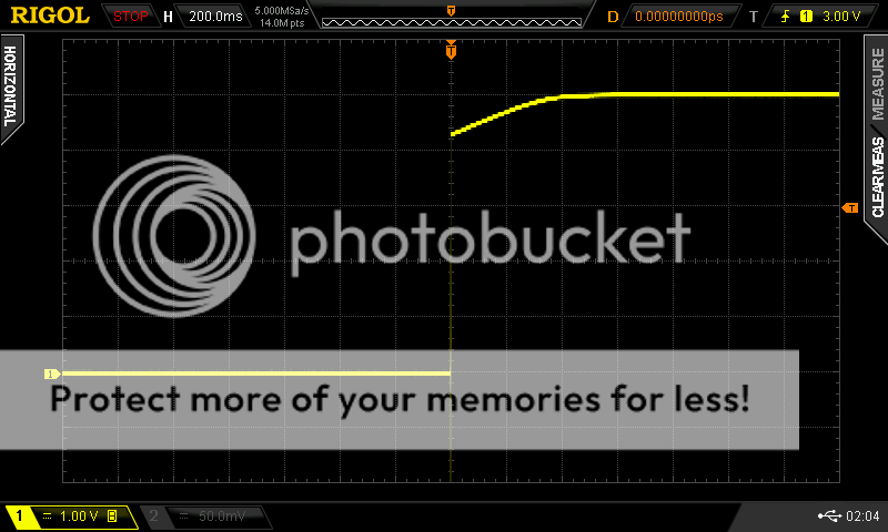
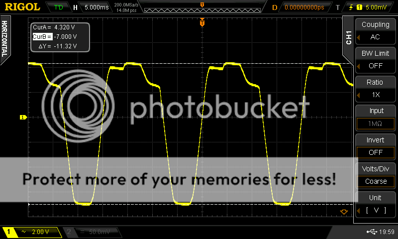
5V set output during mains switch on
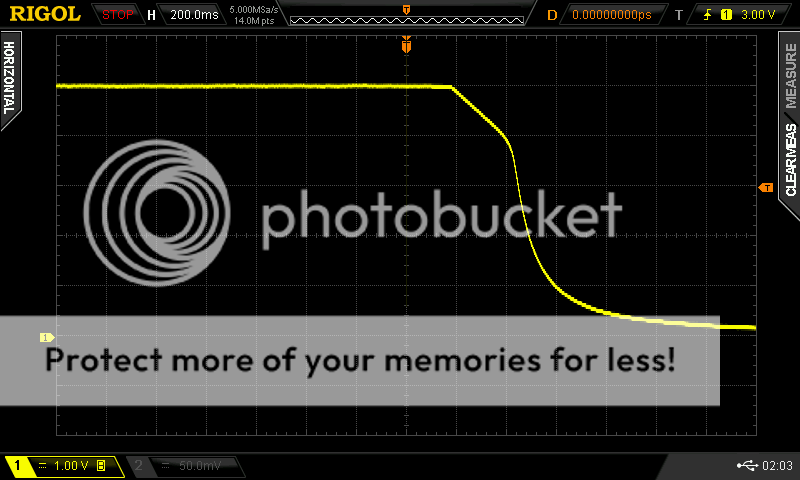
5V set output during mains switch off
Rectification cycle across one bridge forming diode. No ringing.
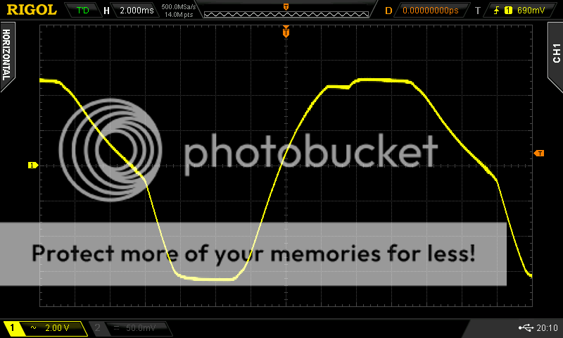
Same as above when zoomed in.
Playing around a Reflektor-D proto these days. Its a configuration idea focused on being handy for powering digital circuits.
To can run 300mA, 400mA, 500mA, 600mA CCS with standard predetermined Rset values using board-level sinks. In combination with proper off-loading by the client circuit's draw of course.
For 3.3V, (3.6V), 5.0V, (7.0V) by combining LEDS mainly. With same parts beyond the CCS and Vref setting ones.
Good stuff I see for now: Steady Vo after very little negative drift from cold to hot only 0.05V, zero overshoot on/off behavior (essential not to kill DAC chips etc.).
Easy to build. No rectification ripple, EMI, or self oscillation appearing on the output over a 200MHZ bandwidth. 20MHZ wide-band noise same as the scope's self limit.
Accepts AC when hosting bridge diodes and a main capacitor filter, or accepts raw DC to a connector and decoupling where the main capacitor would otherwise be.
Proto build and spare board
5V set output during mains switch on
5V set output during mains switch off
Rectification cycle across one bridge forming diode. No ringing.
Same as above when zoomed in.
hello Salas!
Very nice boards!!!
Is there any difference between using leds or rf diodes on the Vref?
What would be the price for one board?
Very nice boards!!!
Is there any difference between using leds or rf diodes on the Vref?
What would be the price for one board?
Very interesting. What are the changes in the schematic?
Its the regular Reflektor-D we recently discussed. Working on proper configuration testing.
hello Salas!
Very nice boards!!!
Is there any difference between using leds or rf diodes on the Vref?
What would be the price for one board?
Different impedance, usually more. About noise they are good. Maybe there will be a diode also in one of the settings (3.6V).
Somewhere in the neighborhood of SSHV2 I guess. Its bigger like 128x54x2mm in matte black. Verification of settings and temperatures with parts likely from Mouser & Digikey are to be finalized now so to write a small build guide on predictable stuff. Trying to can include it in the (belated) general GB iteration people have been asking for a couple of months now.
I have got my hand on some k117 with idss between 3.6-6ma.
What idss should i use for the jfet on the ccs side? Same issue for the jfets paralleling the current mirror.
Thanks
What idss should i use for the jfet on the ccs side? Same issue for the jfets paralleling the current mirror.
Thanks
Its the regular Reflektor-D we recently discussed. Working on proper configuration testing.
Did not find the schematic.... can you help please ?
I have got my hand on some k117 with idss between 3.6-6ma.
What idss should i use for the jfet on the ccs side? Same issue for the jfets paralleling the current mirror.
Thanks
4-5.5mA for 82 Ohm RR
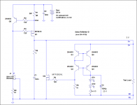
What do you mean JFETs around the current mirror? There are only BJTs there. Low noise PNPs. Use medium to high HFE 10% tolerance.
Did not find the schematic.... can you help please ?
That is the one that will be in the guide. (The board details and instructions finishing very soon).
Attachments
Running it on a makeshift step-load I found no ringing at all. 🙂
1. BJT step load on breadboard with crappy wiring.
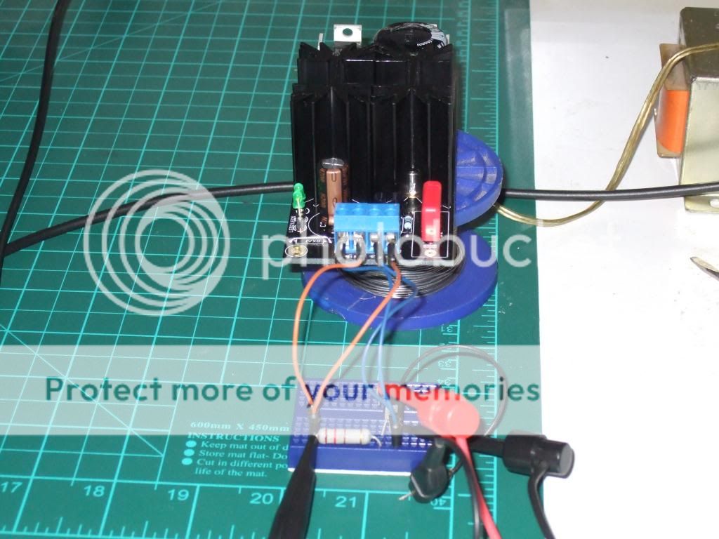
2. Reaction on the active load's local node for the stuff shown in the previous picture.
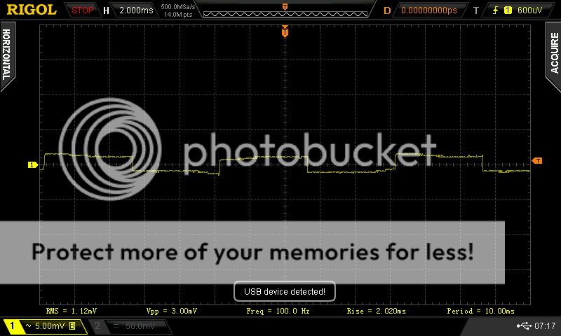
3. Reaction on the active load's local node when using TENMA linear lab PSU (KORAD) instead.
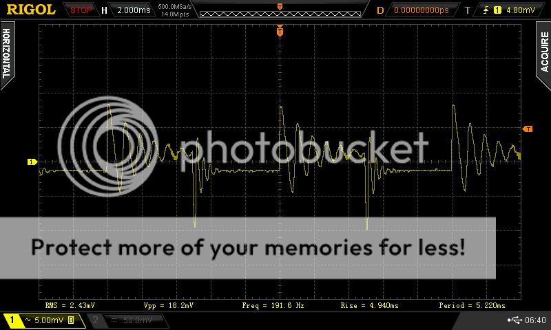
Both pictures taken whith the BJT driven by the same 100Hz square signal coming from the bench function generator.
(The scope measures half period on the 2nd pic because it triggers on a middle of the road ripple).
1. BJT step load on breadboard with crappy wiring.
2. Reaction on the active load's local node for the stuff shown in the previous picture.
3. Reaction on the active load's local node when using TENMA linear lab PSU (KORAD) instead.
Both pictures taken whith the BJT driven by the same 100Hz square signal coming from the bench function generator.
(The scope measures half period on the 2nd pic because it triggers on a middle of the road ripple).
That is the one that will be in the guide. (The board details and instructions finishing very soon).
Salas...where do you get the 2SK880GR for less than an arm and a leg ?
Salas...where do you get the 2SK880GR for less than an arm and a leg ?
Digikey has 8,705 2SK880BL in stock. Use higher RR degeneration for 2mA CCS and its the same thing.
- Status
- Not open for further replies.
- Home
- Amplifiers
- Power Supplies
- The simplistic Salas low voltage shunt regulator